Featured

July 6, 2017
locomotive-train-washing-bay-systems.jpg

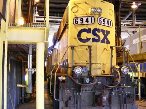
Locomotive train washing bay systems

Our arch locomotive wash systems are very robust with high efficiency pumping systems, stainless steel control panels, galvanized arch piping, and stainless steel nozzles.

It can be designed with multiple arch systems for wetting, washing, and rinsing. For our three-arch system, the train passes through an initial wetting arch with a dilute soap mixture at a very slow speed. The train then moves through the wash arch, which sprays wash water with soap around the full circumference of the locomotive as it passes. At the exit end, the locomotive passes through the rinse arch, which sprays rinse water around the full circumference of the locomotive.

Nozzles in the arches are sized to provide more intense cleaning on the undercarriage and front while minimizing intense water intrusion on more sensitive areas of the locomotive. Depending on the application, total wetting, wash and rinse duration can run between 2-10 minutes.
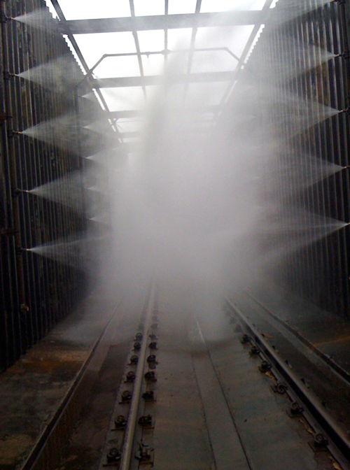
Locomotive High Efficiency Pumping System

These locomotive wash systems can be designed for manual or automatic operation. For a manual system, an onsite operator turns on and off the pump stations for the arches as the locomotive passes.

For an automated system, industrial infrared photocell systems are installed at the entry and exit of the wash building or arches to monitor train movement. The automated control system initiates the wetting, wash and rinse processes and automatically cycles the pumps as needed.

Depending on the application, the locomotive wash equipment provided may include:

  • Skid-mounted high-efficiency pump stations with heavy-duty wash and rinse pumps
  • Water supply tanks with level switches for pump safety and fill control
  • Industrial photocell system for start/stop
  • Traffic light for engineer to view
  • Master control system to manage pumps, chemical metering pumps, photocells, and lights
  • 360-degree arch systems with frames
  • Stainless steel manifolds and stainless steel nozzles
  • Soap metering system to manage soap concentration in wash system
  • pH control systems to manage pH fluctuations due to acids and cleaners
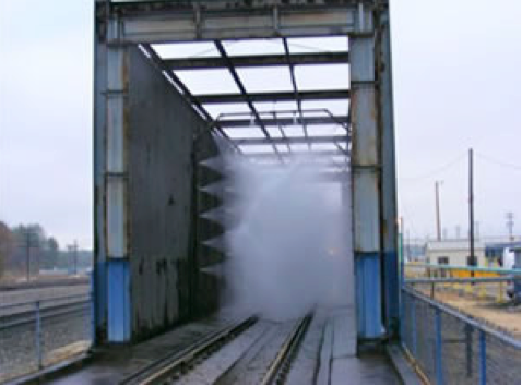
Locomotive Washing Systems

Additional controllers are available that would enable the wash process to start only for those locomotives that desired to be washed, while permitting other trains to traverse the building without starting the wash cycle.

Following the washing, the wash water can be treated for discharge to the sewer or reclaimed for re-use.
June 9, 2017

Port Authority Wash System Case Study

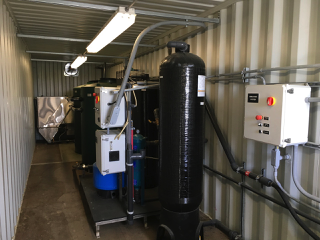
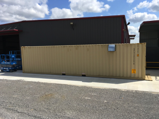
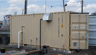
transportable equipment room for port authority

Problem: An international engineering design firm working with a Port Authority contacted us to help them design an equipment and truck wash. The Port had an old wash pad that was too small and old wash equipment that no longer worked very well. The Port needed a larger pad and updated washing and water treatment equipment to accommodate the washing of their existing fleet.

They had the option of either building the wash system with either a closed loop wash water treatment system or a sewer discharge treatment system since they had sewer access but it was quite a distance to the sewer connection.

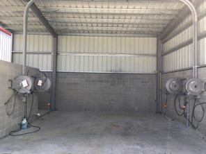
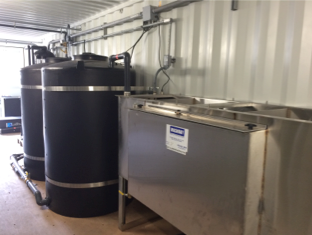
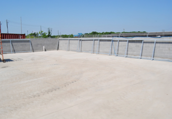
Solution: Wash Bay Solutions helped the engineering firm develop the design for the wash pad, solids settling system, the wash system and two options for water treatment. For both options, we designed the wash and treatment systems to be installed in a portable transportable equipment room to make it simple and cost effective to install. Requests for Quotations were put out for both options and the electric hot water pressure washing system with the SPT-10 Clarifier oil water separator for sewer discharge turned out to be the most cost effective for this particular location with in the port.

We coordinated with the construction company while they were building the wash pad, settling system and sewer connection line. When they were ready, we shipped up the 20’ transportable equipment room (TER-20) and helped them install it in place and get it up and running within a couple days time!

equipment room and oil water separator

wash pad and settling system design


June 9, 2017

Case Study – Rental Equipment
portable equipment room

Problem: An equipment rental company specializing in heavy-duty construction equipment needed to build a wash bay for their haul trucks, dozers and construction vehicles. They had limited inside space in a leased building so they needed a to put all of the equipment inside a portable equipment room that they could pick up and move if needed. Due to their location in a remote area with no sewer connection, they needed a closed loop wash water treatment system.

The company called and asked us to build a heavy-duty, self-contained washing system and help them design the wash pad and solids settling area.

Solution: We had worked with this client for years so we were well aware of the washing and solids handling complications associated with heavy construction equipment. With input from the client, our engineers designed a wash pad design and solids settling system that fit into a rather tight footprint.

All of the wash equipment including a closed loop wash water reclaim system, an electric pressure washing system, and a demucking system was installed in a 40’ Transportable Equipment Room (TER-40) and located adjacent to the wash pad. This saved building costs, preserved valuable warehouse space and will allow them to move the entire system to a different facility if needed.

wash pad design

transportable equipment room


April 19, 2017

C 130 Wash Bay System

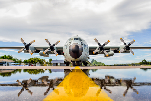
What we have been working on…C-130 Aircraft Washing

A major engineering firm contacted us to help them develop a complete wash bay system for C-130 aircraft. To accommodate both the military’s washing specifications and maximize the washing process, we helped design a very effective aircraft washing system with a combination of foaming, washing and rinsing equipment.

When the foaming process is desired, the operator moves a portable foamer to the desired location near the aircraft. After selecting either hot or cold water for the foamer from the remote switch at the reel, the operator can spray thick foam up to a height of approximately 40 feet to reach the highest point on the aircraft.

For washing and rinsing the aircraft, the operator will use either the pressure washer or water cannon on either side of the aircraft and select either hot or cold water. They can be used separately or at the same time, and use either hot or cold water independently of the other.

All of the hose reel systems include remote control capabilities, and the system can be programmed to permit a combination of foaming, washing or rinsing to occur at any one time.

All of the wastewater from the foaming, washing and rinsing operations will be treated by a closed loop wash water reclaim system. The reclaim system will filter and disinfect the water, and store the clean, recycled water so that it is available for use for all washing, rinsing, and foaming applications as desired.

The recycling system includes a fresh water bypass manifold system that enables the operator to manually switch the entire system over to fresh water if necessary or desired. It also automatically replenishes itself to maintain a minimum volume of water to make up for any losses to the system from evaporation or carry-off.

A stainless steel evaporator is included in the system design to serve two functions: elimination of excess water accumulation in the overall system and to periodically dispose of water in the system to allow for fresh water addition to maintain optimum water quality. Both of these functions are programmed to automatically occur, and can be adjusted to meet the preferences of the system operator.


June 14, 2016

Our new 60 gpm nozzle and trolley assembly

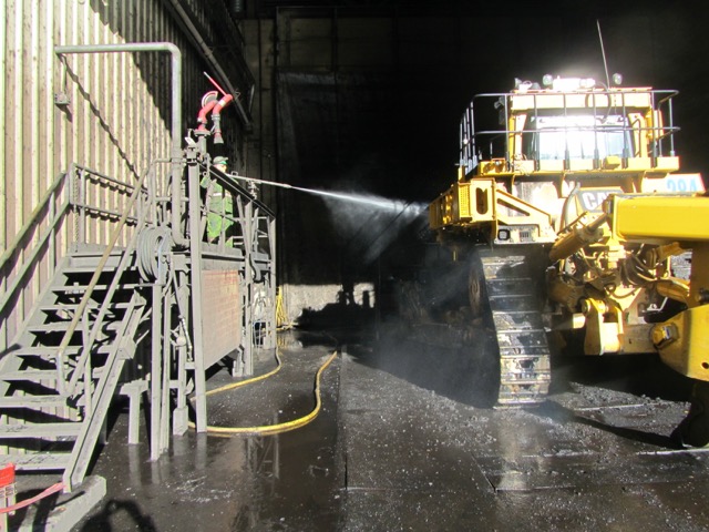
Problem: A mining company was washing and de-icing their large mining equipment with a 150-200 gpm water cannon monitor system. In the summer, washes typically averaged 1-2 hours, using 9,000 to 24,000 gallons per vehicle.

In the winter months, however, the company used the same water cannon monitor system to defrost the equipment and then wash it. Defrosting in the depths of winter could often take up to 10 hours which added an additional 90,000 to 120,000 gallons per vehicle!

The company called Wash Bay Solutions and asked us to develop a heavy-duty washing solution that would greatly reduce their water usage.

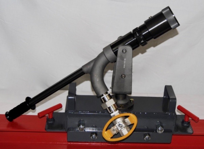
Solution: With input from the client, our engineers enhanced our existing demucking system with a new nozzle design to produce our 60 GPM @ 1000 PSI Mighty Monitor system.

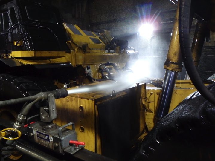
The key to this system is our specially designed, multi-directional, 60 gpm @ 1000 psi nozzle. These nozzles are trolley-mounted so they can ride along I-beam systems, immediately adjacent to the vehicle. Specialized hose trolley systems attached to the nozzles allow the operator to wash the 60-ton mining vehicles almost single-handedly!

These nozzles are trolley-mounted so they can ride along I-beam systems, immediately adjacent to the vehicle.

Results: The client is very happy the ease-of-handling, range of movement, and washing power of the new design. They are able to wash their large trucks quickly and effectively, using less time and about 1/10 of the amount of water than they did with the water cannons.


February 19, 2016
low-flow-demucking-system.jpeg

Low Flow Demucking System
Using only 60 gpm of reclaimed water, our Mighty Monitors will effectively remove heavy accumulations of dirt and mud – saving thousands of gallons of water per cleaning.

Get the power of a fire hose with a fraction of the water usage!

Robustly designed for heavy industrial applications such as mining and oilfield services, our MM Series Mighty Monitors are great for cleaning large haul trucks, steel tracked vehicles or any heavy equipment caked with mud, clay, ice, grass or muck.

For drilling and construction equipment applications, our 20 gpm Mighty Monitor system cleans quickly and effectively, in half the time of a typical pressure washer.

Our new 60 gpm nozzle and trolley assembly

For mining applications, we have developed a revolutionary heavy-duty Mighty Monitor system to replace the standard high volume water cannons that have been used for decades. Our systems combine increased pressure and specialized nozzles to ensure a quality wash. Using only 60 gpm of reclaimed water, our Mighty Monitors will effectively remove heavy accumulations of dirt and mud – saving thousands of gallons of water per cleaning.

Fast and effective cleaning while saving time, water and water treatment costs – a win-win-win situation!

Mighty Monitor System Features:

  • 20-60 GPM Capacities
  • Uses only a fraction of water used in traditional water monitors or water cannons
  • Emergency Stop System
  • NEMA 4X Control Panel
  • High-Efficiency Diaphragm or Multi Stage Pumps
  • Pressure Gauge
  • Handheld Stream-to-Cone Gun & Wand
  • Trolley-mounted Multi-directional Stream-to-Cone Gun & Wand
  • Can use fresh or recycled water
  • Reduces the amount of water to be treated

Mighty Monitor System Options:

  • UL Listings
  • Remote Motor Controls
  • Optional Heating Systems
  • Optional VFD Systems
  • Optional Automated Wash Monitors
  • Industrial Grade Hose Reels and Stands

MIGHTY MONITOR SYSTEM SPECIFICATIONS

MODEL


MM-20/1000 MM-30/60/1000
FLOW RATE, GPM 20 30 & 60
PRESSURE, MAX, PSI 1000 1000
MOTOR, HP 15 2 @ 30
PUMP TYPE DIAPHRAGM DUAL PUMP DIAPHRAGM
CONTROLS MANUAL/REMOTE MANUAL/REMOTE/VFD/ROBOTIC/PLC
GUN & WAND HAND-HELD STREAM-TO-CONE TROLLEY-MOUNTED MULTI-DIRECTIONAL STREAM-TO-CONE
HOSE 75’ @ ¾” ¾”D, LENGTH DESIGNED TO FACILITY LAYOUT
ELECTRIC 208/480/575 V 3 PH 50/60 HZ 208/480/575 V 3 PH 50/60 HZ
APPROXIMATE DIMENSIONS 18” W x 60” L x 24” H 36” W x 60” L x 24” H

Give us a call for more product information – 800-453-8639


July 28, 2014
fork-lift-fl-series-water-treatment-systems.jpg

Closed Loop Reclaim System for Oil and Gas Industry Equipment
To reduce both hauling costs and water usage, many oil field services companies have installed our Drilling Equipment (DE Series) Systems to treat and recycle their wastewater.

Oil and gas drilling, including hydraulic fracking, is a complicated endeavor. The nature of the work ensures that dirt, downhole acids, crude residues, waxes, and grease coat down-hole motors, pumps, subs, drill pipe, tanks, and vehicles.  Constant washing and NDT testing is essential to maintaining the equipment in good working order.  These processes, however, produce an enormous amount of water. Often, the wastewater is stored onsite and disposed of every few weeks – which can get very expensive.

To reduce both hauling costs and water usage, many oil field services companies have installed our Drilling Equipment (DE Series) Systems to treat and recycle their wastewater. Robustly designed and manufactured for the oil and gas industry, our heavy-duty, multi-stage treatment systems clean up the water for re-use or discharge.  By simplifying the water handling, many clients are able to both increase production and reduce costs, resulting in pay back periods of only months!

The important first stage is the solids handling system. Depending on the amount of solids and the wash pad design, our engineers will develop a site-specific system to remove as many solids as possible before the water goes to the filtration systems.

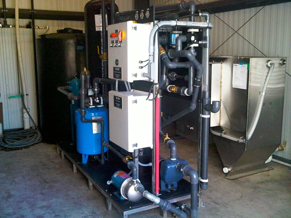
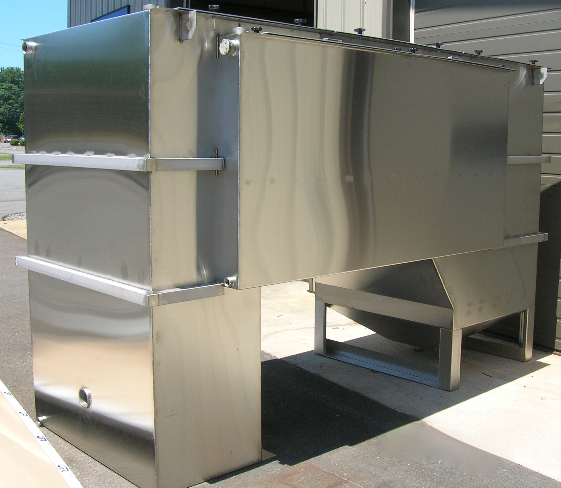
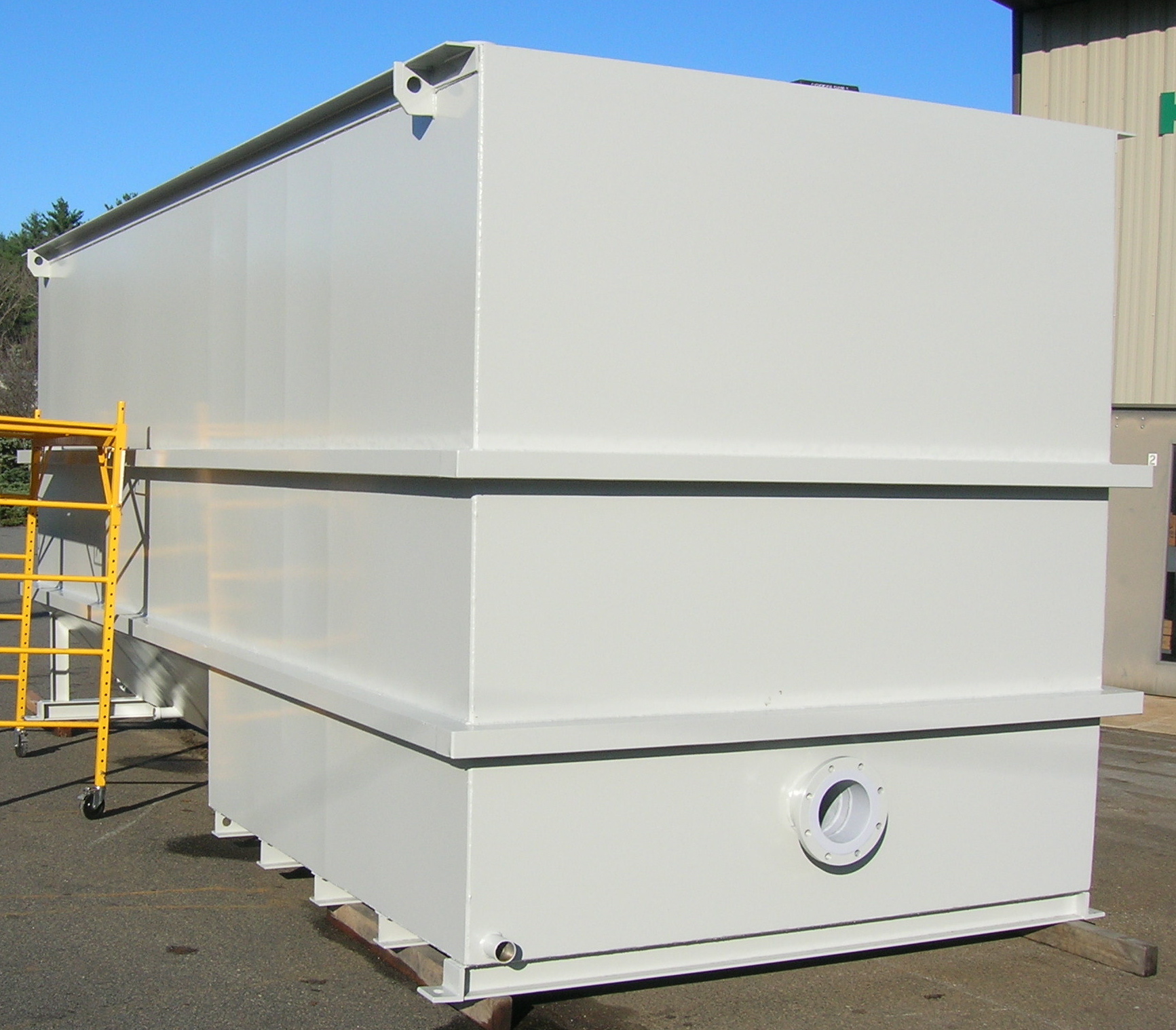
The next stage of the system is the stainless steel clarifier oil water separator which removes most suspended solids (TSS), essentially all settleable solids and all free and dispersed non-emulsified oils from the waste stream.

Depending on the application, the next stage could be biological treatment. Our proprietary biological filter system uses a revolutionary, patented US technology, including specifically developed microbes combined with a highly efficient aeration technology, to treat the water and remove substantially all of the COD and FOG in the water.

In the final polishing stage, the water goes through an extremely efficient filtration process utilizing fully automated solids filtration and a proprietary blended activated carbon (GAC) polishing filtration, and a corona discharge ozone generator to prevent odors. Processed water passing through the system will be free of particles greater than 10 microns in size, substantially all emulsified oils, waxes and other volatile organic compounds.

STANDARD DE Series SYSTEM FEATURES:

  1. Stainless Steel Construction
  2. High-Efficiency Pumps
  3. Corona Discharge Ozonation System
  4. Solids Handling & Separation
  5. TSS, COD, FOG Reduction
  6. Multi-Stage / Multi-Pass Filtration
  7. Pressurized Blended Carbon Polishing Filters
  8. Auto-Backwashing Filters
  9. NEMA 4X Control Panel with PLC controller

Depending on the location, many options are available to maximize the efficiency of the wastewater treatment system including:

OPTIONAL FEATURES:

  1. SCADA and remote monitoring
  2. UL/CSA Listing
  3. Transportable equipment rooms
  4. Rain Diverter Systems
  5. Biological Treatment
  6. Rain Water Harvesting Systems
  7. Chemical/Acid/Salinity Resistant Pumps & Components
  8. ORP / pH/ Salinity control system

DE SERIES SYSTEM SPECIFICATIONS

MODEL DE 10/10 DE-30/20 DE-60/50 DE-100 DE-200
FLOW RATE, GPM 1-10 1-30 10-60 30-100 60-200
COALESCING MEDIA, CUBIC FT 4 8 24 48 96
CARBON BLEND MEDIA, CUBIC FT 6 18 50 100 200
RE-CIRCULATION PUMP, HP 1.5 3 3 5 5
RE-PRESSURIZATION PUMP, HP 1 3 5 7.5 10
OZONE SYSTEM Up to 32 grams of ozone per hour
CONTROL SYSTEM PLC, Automatic, Manual or Off
PUMP FRAME SIZE 34” W X 66” L 34” W X 96” L
POWER REQUIREMENTS 208 / 240 v 1 ph  or 208 / 240 / 480 v 3 ph
* LARGER CAPACITY SYSTEMS (500-1500 GPM) ARE AVAILABLE

July 28, 2014
4-vessel-Filter-System.jpg

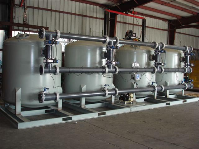
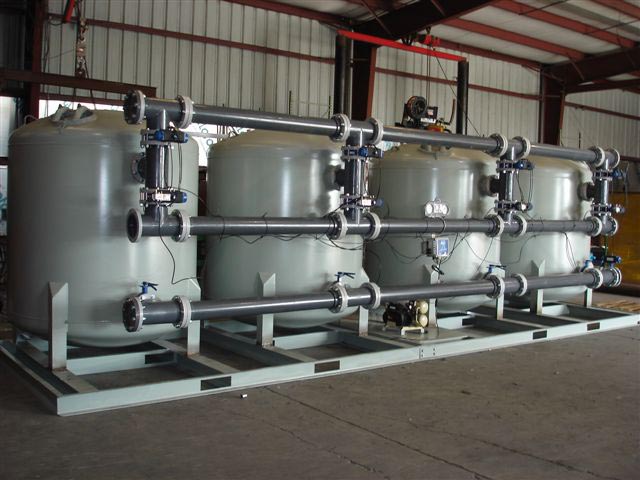
4-Vessel Filter System
4-Vessel MINING & CONSTRUCTION (MC Series) TREATMENT SYSTEMS

As the demand for minerals and precious metals grows, mining companies are constantly working to keep up with demand and improve their mining methods while at the same time doing as much as they can to preserve the environment.  Most mining and heavy construction work is predominantly done by heavy equipment such as LHD loaders, backhoes, excavators and dump trucks. This equipment gets coated with solids, dirt and grime on a daily basis.

Daily washing is an important part of maintaining the equipment in good working order.  This washing, however, produces a lot of dirty water and solids. The most efficient way to reduce your water usage and hauling costs is to remove the solids and recycle the water.

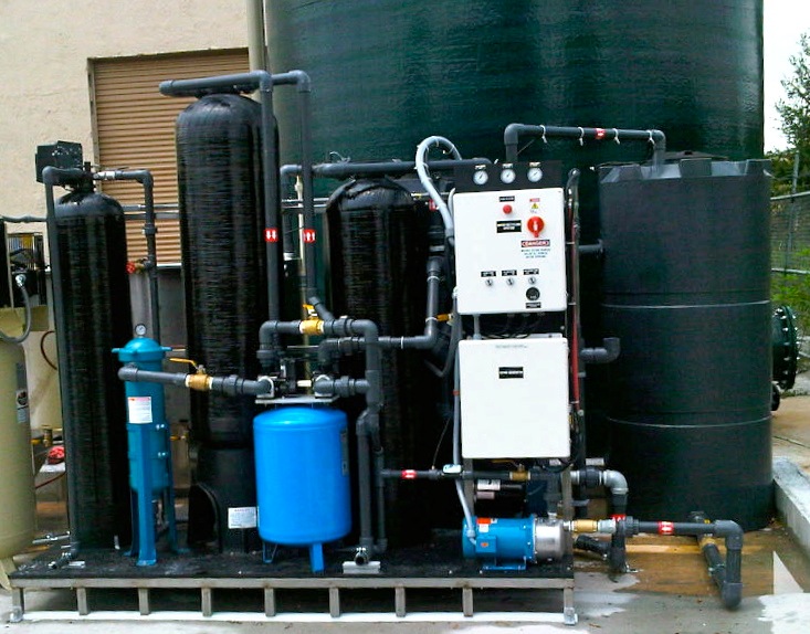
Our Mining & Construction Equipment (MC Series) Systems are heavy-duty, multi-stage reclaim and discharge systems, engineered and manufactured for the mining and heavy construction industries.

Because of the enormous amount of solids generated by the washing process, the most critical first stage for these systems is the solids handling system. Depending on the wash pad design, our engineers will develop a site-specific system including sumps, trenches, screens and skimmers to remove as many solids as possible before the water goes to the subsequent filtration systems.

After many of the heavy solids are removed in the first stage, the water will then be processed through a stainless steel clarifier oil water separator which removes most suspended solids (TSS), essentially all settleable solids and all free and dispersed non-emulsified oils from the waste stream.

After the clarifier separator, the water can either be discharged or further processed for re-use.  If the water needs to be re-used, the water then goes through an extremely efficient filtration process utilizing fully automated solids filtration and a proprietary blended activated carbon (GAC) polishing filtration, and a corona discharge ozone generator to prevent odors. Processed water passing through the system will be free of particles greater than 10 microns in size, substantially all emulsified oils, waxes and other volatile organic compounds.

MC SERIES STANDARD FEATURES:

  1. Stainless Steel Construction
  2. High-Efficiency Pumps
  3. Corona Discharge Ozonation System
  4. Solids Handling & Separation
  5. TSS & FOG Reduction
  6. Multi-Stage / Multi-Pass Filtration
  7. Pressurized Blended Carbon Polishing Filter
  8. Auto-Backwashing Filters
  9. NEMA 4X Control Panel with PLC controller

Depending on the location, many options are available to maximize the efficiency of the wastewater treatment system including:

OPTIONAL FEATURES:

  1. Can be configured with existing equipment
  2. SCADA and remote monitoring
  3. UL/CSA Listing
  4. Transportable equipment rooms
  5. Rain Diverter Systems
  6. Rain Water Harvesting Systems
  7. Chemical/Acid/Salinity Resistant Pumps & Components
  8. ORP / pH control system

MC SERIES SYSTEM SPECIFICATIONS

MODEL MC-10/10 MC-30/20 MC-60/50 MC-100 MC-200*
FLOW RATE, GPM 1-10 1-30 10-60 30-100 60-200
COALESCING PLATE AREA, SF 41 124 211 400 600
COALESCING MEDIA, CF 4 8 24 48 96
APPROX. CLARIFIER SEPARATOR SIZE, FT (WxLxH) 3 x 7 x 5 3.5 x 8 x 6 4 x 10 x 6 5 x 11 x 7 7 x 13 x 9
RECLAIM RE-CIRCULATION PUMP, HP 1.5 3 3 5 5
RECLAIM RE-PRESSURIZATION PUMP, HP 1 3 5 7.5 10
OZONE SYSTEM Up to 32 grams of ozone per hour
RECLAIM CONTROL SYSTEM PLC, Automatic, Manual or Off
RECLAIM PUMP FRAME SIZE, FT (WxL)
(TANKS ADDITIONAL)
3 X 6 3 x 8
POWER REQUIREMENTS 208 / 240 V 1 ph   or  208 / 240 / 480 V 3 ph
* LARGER CAPACITY SYSTEMS (500-1500 GPM) ARE AVAILABLE

June 10, 2014
oil-and-solids-water-separation-unit-300x260.jpg

Oil and Solids Water Separation Unit
The Solids and Oil Water Separation Systems (SOWS) are horizontal gravity flow treatment systems designed to separate settleable solids, suspended solids, and free and dispersed oil.

New SOWS Systems Remove Both Free & Dispersed Oil AND Settable & Suspended Solids!

Introducing the new Best Available Technology (BAT) for the treatment of produced water and flow-back water. The Solids and Oil Water Separation Systems (SOWS) are horizontal gravity flow treatment systems designed to separate settleable solids, suspended solids, and free and dispersed oil.

This system is a significant improvement to the currently used CPI Separators which can only separate free oil and settleable solids – allowing a considerable amount of dispersed oil, suspended solids, and stable emulsions to pass through the system.

Applications:

  • Onshore and Offshore Drilling Operations
  • Oil Refineries
  • Produced Water
  • Waste Oil Processing Facilities

Benefits:

  • No moving parts
  • Low maintenance
  • Heavy duty carbon or stainless construction

The SOWS System has 5 stages of separation.

Solids Oil Water Separation

Stage 1, Inlet Area – The water mixture flows into the inlet quiescent area where the velocity of the water slows. The free oil (150 micron in size or greater) separates and rises to the surface where it is removed by a pipe skimmer.

Stage 2, Clarifier/Solids Intercept Section – The settleable solids flow downward and are captured in the clarifier/ solids intercept section.

Stage 3, Inclined Plate Section – The suspended solids and dispersed oil flow upward through the inclined plates section. Most of the suspended solids will slide down these plates into the hopper.

Stage 4, Separation Compartment – The remaining suspended solids and dispersed oil flow into the separation compartment where the coalescing plates remove 99% of the free oil droplets 30 micron or greater. This oil rises to the surface where an oil skimmer decants it to an oil storage tank. The coalescing plates then capture the remaining suspended solids.

Stage 5, Clean Water Compartment – The flow of water will go over the overflow weir into the clean water compartment where oil absorption polishing bags trap any trace oils before the water is discharged.

SOWS Solids Oil Water Separation Systems

Model BPD
(Barrels Per Day)
GPM Width Length Height Inlet
Outlet Dia
Clarifier
Plate Area, SF
Separator
Coalescing Volume, CF
Sludge
Volume (Gal)
Total
Capacity (Gal)
SOWS-150 5,140 150 6′-6″ 20′-0″ 9′-0″ 6″ 600 64 300 4250
SOWS
-200
6,850 200 6′-6″ 20′-0″ 10′-0″ 6″ 800 80 300 4930
SOWS
-250
8,570 250 7′-6″ 20′-6″ 10′-0″ 8″ 1000 96 350 5810
SOWS
-300
10,285 300 8′-6″ 21′-6″ 10′-0″ 8″ 1200 120 400 7040
SOWS
-350
12,000 350 8′-6″ 23′-0″ 10′-0″ 8″ 1400 150 425 7480
SOWS
-400
13,715 400 8′-6″ 24′-6″ 11′-0″ 8″ 1600 150 500 8500
SOWS
-450
15,430 450 9′-6″ 26′-0″ 11′-0″ 8″ 1800 175 525 10020
SOWS
-500
17,140 500 9′-6″ 26′-6″ 11′-0″ 8″ 2000 210 550 10450
SOWS
-550
18,855 550 9′-6″ 28′-0″ 12′-0″ 8″ 2200 210 675 11580
SOWS
-600
20,570 600 9′-6″ 29′-6″ 12′-0″ 10″ 2400 240 700 13240
SOWS
-700
24,000 700 10′-6″ 30′-0″ 12′-0″ 10″ 2800 288 750 15450
SOWS
-800
27,425 800 10′-6″ 31′-0″ 12′-6″ 10″ 3200 324 775 17540
SOWS
-900
30,860 900 10′-6″ 32′-6″ 13′-0″ 12″ 3600 324 800 19260

April 22, 2014
vfd-controlled-multi-gun-high-pressure-cleaning-systems-1280x977.png

VFD Controlled Multi-gun high pressure cleaning systems
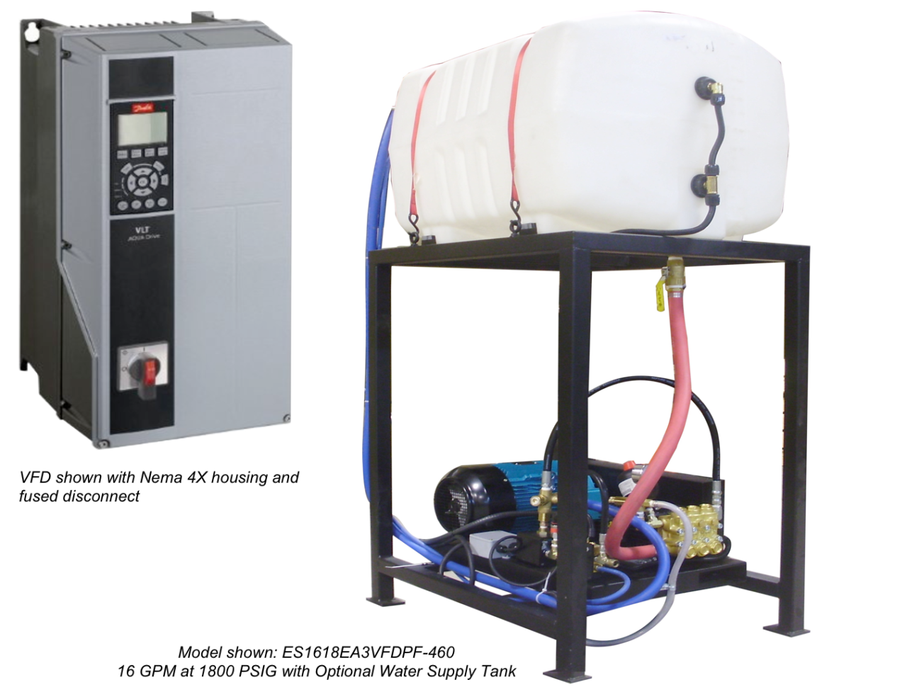
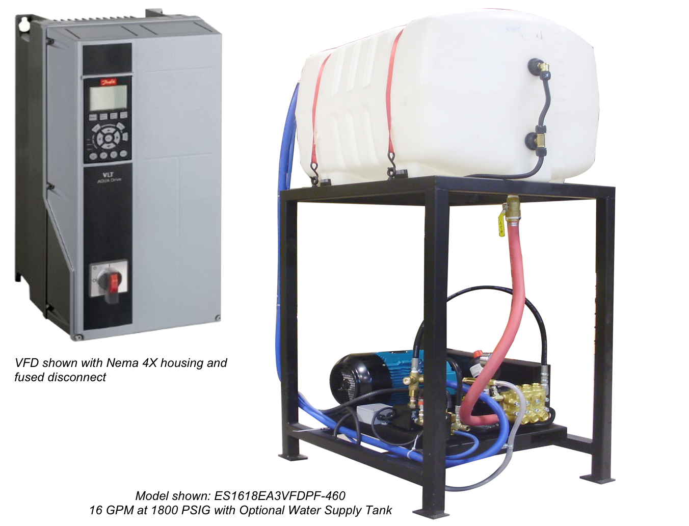
A Variable Frequency Drive (VFD) system is one of the most cost effective units to run and to maintain and they are extremely easy to use.

A Variable Frequency Drive (VFD) system is one of the most cost effective units to run and to maintain and they are extremely easy to use. The VFD display makes is simple to trouble shoot. The VFD display shows various input signals which can be used to visually display and indicate system faults. The VFD system offers substantial operational and maintenance savings. A variable frequency drive extends the life of the motor, pump, and pump components. A VFD significantly reduces maintenance or service related issues. The system will only utilize the power (speed of motor and pump) to match the output demands. For example: A 20 gpm system, set up for 4 users at 5 gpm each. If there is only one user on the system outputting 5 gpm, the motor/pump will only turn at 1/4” speed to meet that demand. The VFD system shows a savings in energy costs to run the system, it only uses what it needs. On system start-ups, a VFD controlled system slowly ramps up speed to the minimal required rpm to meet the initial demand. This eliminates the huge inductive amperage load a system with standard controls requires when starting. A VFD system does not require the use of motor contactors, overloads, and fusing.

VFD benefits

  • Energy savings
  • Smoother quieter operation, eliminate water hammer
  • Extend pump life
  • Extend system component life
  • Extend motor life
  • Reduce maintenance

Functional Design

  • Real-time system monitoring and control (wash station duty cycle/activity, low inlet water supply and system pressure loss shutdown, and high water temperature shutdown)
  • Compact and versatile design allows for installation in virtually any location/environment
  • Systems designed/built to application requirements – provides for increased productivity
  • VFD increases or decreases pump/motor speed to meet the demands of single and or multiple users

Standard Equipment

  • Belt-driven, industrial-duty plunger or piston pump with multi-gun pressure regulator, pilot-activated flow switch, factory-set pressure relief valve and liquid-filled pressure gauge
  • VFD controlled with performance display screen, Nema 4x housing, and a fused disconnect
  • Premium-efficiency, inverter-duty motor (IP55, Class B temp. rise, Class F insulation, 40° C ambient temp. design)
  • I/O/M (Installation/Operation/Maintenance) manual

North Carolina

Headquarters

At WashBaySolutions.com, we have been specializing in high tech, custom-engineered solutions to complex washing and wastewater issues since 1991.
+ 1 800-453-8639

WashbaySolutions.com

sales@washbaysolutions.com

GET IN TOUCH

Follow Our Activity

Get the latest news, product updates and case studies all happening here: