Above Ground Oil Water Separator Specifications and Drawings
PART 1 – GENERAL
1.1 DESCRIPTION: The Wash Bay Solutions (WBS) oil/water separator Model
__________ shall be a prefabricated rectangular unit of the parallel corrugated plate
gravity displacement type as specified herein and as described in API Publication 421.
1.2 APPLICATION: The oil/water separator shall be designed for gravity separation of
non-emulsified oil and some settleable solids from the wastewater stream. The
separator is designed to receive oily water by gravity/pumped flow that will not
mechanically emulsify the oil and will process it on a once through basis. The source of
the influent to the separator shall be flow from___________ [describe the application or
process].
1.3 PERFORMANCE: The oil/water separator shall remove essentially all free and
dispersed non-emulsified oil from the water stream and produce an effluent containing
less than ___ mg/l of oil droplets larger than ___ microns.
1.4 INFLUENT CHARACTERISTICS: The oil/water separator is designed for a
maximum average flow of __ gallons per minute (gpm). The influent is further
characterized as follows:
Operating Temperature ___ °F
Specific Gravity of Oil ___
Specific Gravity of Water 1.0
Specific Gravity of Solids ___
1.5 DESIGN CRITERIA: The oil/water separator shall be designed in accordance with
Stokes Law and API Bulletin No. 421.
1.6 INSPECTION AND QUALITY ASSURANCE: The oil/water separator shall be
fabricated, inspected and tested for leakage before shipment from the factory as a
completely assembled system ready for installation.
1.7 SUBMITTALS: Shop drawings for separators shall be submitted and shall show
principal dimensions and locations of all fittings. Design calculations shall be provided
and shall reflect that oil/water separator is in conformance with effluent requirements
when operating under detailed influent conditions. These calculations should show oil
rise rate, overflow rate, Reynolds Number and removal efficiency. Shop drawings shall include brochures, catalog cuts, operations and maintenance instructions, dimensions,
and location of accessories.
1.8 DESIGN DATA: An analysis shall be submitted which indicates that, at the calculated overflow rate, the separator will be provided with the required square feet of projected plate separation area to achieve the specified performance under laminar flow (i.e. Reynolds number of less than 500) conditions. Calculations shall take into account the rate of flow, influent concentrations, particle characteristics, fluid temperature, and fluid specific gravities.
PART 2 CONSTRUCTION
2.1 FABRICATION: The oil water separator shall be a special purpose prefabricated
parallel corrugated plate, rectangular, gravity displacement, type oil water separator.
The separator shall be comprised of a tank containing an inlet compartment, separation
chamber, sludge chamber, and clean water outlet chamber.
2.2 TANK: The tank shall be a single wall construction of 12 gauge stainless steel
conforming to ASTM A240, type 304 stainless steel. Welding will be in accordance with
AWS D1.1 to provide a watertight tank that will not warp or deform under load.
2.2 PIPE CONNECTIONS: All connections 3” and smaller shall be FNPT couplings. All
connections 4“ and larger shall be flat face flanges with ANSI 150 pound standard bolt
circle. Flanged piping connections shall conform to ANSI B16.5.
2.3 SEPARATOR CORROSION PROTECTION (For Carbon Steel Only): After the shop
hydrostatic test has been successfully completed, a coating system will be applied to
the interior and exterior surfaces of the separator. Interior and exterior shall be
sandblasted to SSPC-SP10 & SSPC-SP6; Interior shall be lined with Tnemec Series 61 liner to 9 mils MDFT; Exterior shall be coated with polyamide epoxy to 6 mils MDFT.
2.4 LIFTING LUGS: The tank shall be provided with properly sized lifting lugs for
handling and installation.
2.5 COVERS: The tank will be provided with vapor tight covers for vapor control. Gas
vents and suitable access openings to each compartment will be provided. The covers
shall be constructed of marine grade aluminum and will be fastened in place. A gasket
shall be provided for vapor tightness. 3/8-16 bolts and threaded knobs will be provided
for cover attachment.
2.6 INLET COMPARTMENT: The inlet chamber shall be comprised of a non-clog
diffuser to distribute the flow across the width of the separation chamber. The inlet
compartment shall be of sufficient volume to effectively reduce influent suspended
solids, dissipate energy and begin separation. The media will sit elevated on top of a sludge baffle. The sludge baffle will be provided to retain settleable solids and sediment
from entering the separation chamber.
2.7 SEPARATION CHAMBER AND MEDIA: The oil separation chamber shall contain
the required amount of coalescing media that is sufficient for the removal of a minimum
of 99.9% of free droplets 20 micron in size or greater at the designed flow rate. The
elements (plates) of the media shall be positioned to create an angle of repose of 90
degrees to the horizontal or longitudinal axis of the separator to facilitate the removal of
solids from the coalescing surfaces, which would increase velocities to the point of
discharging an unacceptable effluent. The media shall have a minimum of 87% void
volume to facilitate the settling of sludge and dirt particles in the sludge compartment.
Laminar flow with a Reynolds Number of less than 500 at a maximum designed flow
rate shall be maintained throughout the separator so as to prevent re-entrainment of oils
with water. Flow through the coalescing media shall be crossflow perpendicular to the
vertical media elements such that all of coalescing media is available for contact with
the oily water.
2.8 BAFFLES: The tank shall be provided with an oil retention & underflow weir, and
overflow weir. The underflow weir shall be positioned to prevent re-suspension of
settled solids. The baffle shall be constructed to ASTM A240 stainless steel plate of
same thickness as tank.
2.9 SLUDGE HOPPER (AS REQUIRED): The sludge hopper shall be located prior to
and under the coalescing compartment for the settling of any solids. It shall also prevent
any solids from entering the clean water chamber.
2.10 OIL SKIMMER: The oil separation chamber will be provided with at least one
rotatable pipe skimmer for gravity decanting of the separated oil to a product storage
tank.
2.11 CLEAN WATER CHAMBER: The tank shall be provided with a clean water
chamber that allows the water to leave the separator by gravity flow through the clean
water outlet port.
2.12 VENTS: The tank shall be provided with sufficient adequately sized vents for vent
piping to atmosphere.
2.13 SAMPLING PORTS (AS REQUIRED): The tank shall be provided with sufficient
adequately sized sample ports to permit easy access for obtaining water samples.
PART 3 – EXECUTION
3.1 DELIVERY AND STORAGE: All materials delivered to site shall be inspected for
damage. Materials shall be stored on site in enclosures or under protective coatings and
adequately protected to prevent damage during periods of inclement weather, including subfreezing temperatures, precipitation, and high winds. All materials susceptible to deterioration by direct sunlight shall be stored under cover to avoid damage due to high temperatures. No materials shall be stored directly on the ground. If special
precautions are required, prominent and legible instructions for such precautions shall
be marked on the outside of equipment or it’s crating.
3.2 HANDLING: Handling and placing of coated steel tanks shall be done with care and
in a manner that will minimize damage to the coating and will not reduce the protective
effectiveness of the coating. Do not drag materials. The coated tanks shall be placed
carefully in position with a minimum of handling. All damaged surfaces, which occur
during these operations, shall be repaired at the expense of the Contractor.
3.3 INSTALLATION: The oil water separators shall be installed as shown on the
drawings and in strict accordance with the manufacturer's recommendations.
3.4 INSPECTION: Examine each component of separator for compliance with
requirements as specified. This element of inspection shall encompass visual
examinations and dimensional measurements. Noncompliance with specified
requirements, or presence of one or more defects preventing or lessening maximum
efficiency of separator operations, shall constitute cause for rejection.
3.5 PRETEST PROCEDURES: After separator has been leveled, hydrostatically test
unit for four (4) hours by filling full with potable water, provided by Customer, with
means of getting it from the nearest source by the Contractor. Acceptance criteria for
this test is no leakage after four (4) hours.
3.6 TESTING: After the hydrostatic test has been successfully completed and unit has
been properly connected to influent and effluent piping, the Contractor shall inject the
influent oil/water mixture of ___ ppm into separator filled with potable water. After initial
injection, the unit shall be operated for a minimum of ten tank volume changes prior to
testing for contaminant removal.
3.7 TESTS FOR CONTAMINANTS: The Contractor shall test the effluent to ensure
that it meets the required oil concentration levels. Tests shall be performed by an
independent certified testing laboratory.
3.8 ANALYTICAL METHODS: Test and sample preservation methods for test
contaminants shall be in accordance with the latest revision of EPA Methods for
Chemical Analysis of Water and Wastes.
3.9 TEST REPORTS: Testing reports or Manufacturer's Certificate of Performance
Compliance shall be submitted. If testing indicates that the system does not meet
design requirements, all corrective measures shall be taken as necessary to achieve
design requirements.
PART 4 – WARRANTY
4.1 TANK AND ACCESSORIES: The oil/water separator tank and all accessories shall
be provided with a five (5) year warranty for defective equipment.
4.2 TREATMENT EQUIPMENT AND ACCESSORIES: All treatment equipment and
accessories supplied as part of the oil/water separator system shall contain a one (1)
year warranty for defective equipment.
PART 5 – REFERENCES
The publications listed below form a part of this specification to the extent referenced.
The publications are referenced to in the text by basic designation only.
5.1 AMERICAN PETROLEUM INSTITUTE (API): API Publication 421, "Monographs
on Refinery Environment Control – Management of Water Discharges, Design and
Operation of Oil-Water Separators".
5.2 AMERICAN WELDING SOCIETY (AWS) STANDARDS: D1.1-92 Structural
Welding Code-Steel.
5.3 AMERICAN SOCIETY FOR TESTING AND MATERIALS (ASTM) STANDARDS:
A36-93 Structural Steel
5.4 AMERICAN NATIONAL STANDARDS INSTITUTE (ANSI) STANDARDS: ANSI
B16.5-88 Pipe Flanges and Flanged Fittings
5.5 EPA METHODS FOR CHEMICAL ANALYSIS OF WATER & WASTEWATER:
16th Edition (1985) – Section 503A
5.6 STEEL STRUCTURES PAINTING COUNCIL (SSPC) STANDARDS: SSPC-SP10
Near-White Blast Cleaning
5.7 NATIONAL ASSOCIATION OF CORROSION ENGINEERS (NACE) STANDARDS:
Standards for Interior and Exterior Surfaces
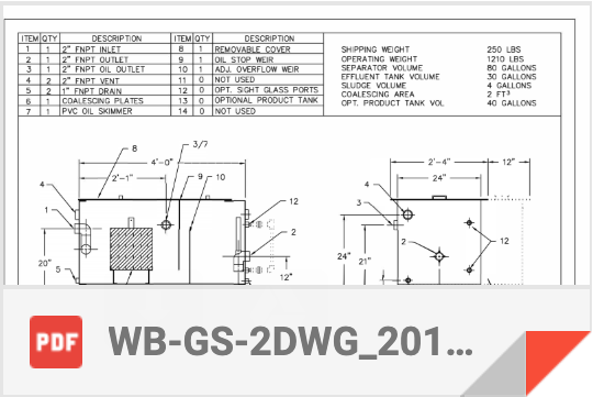
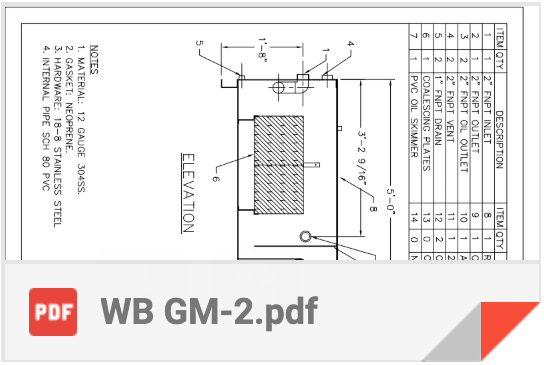
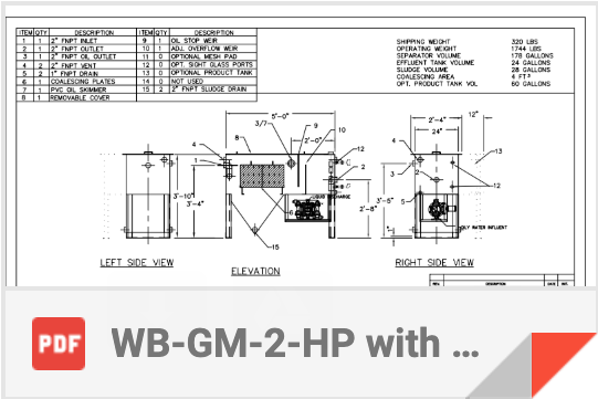
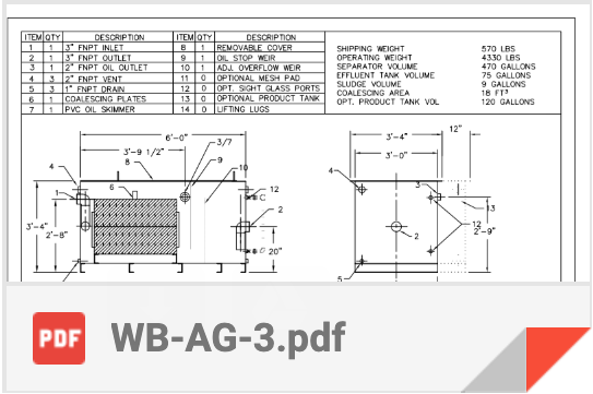
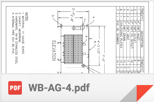
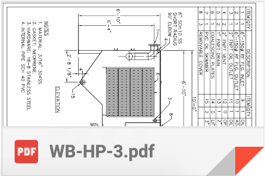
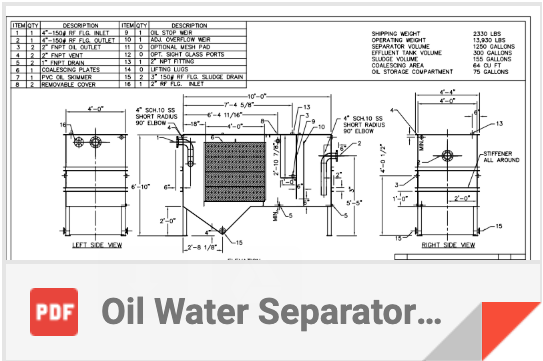
Drawings
Below, please find drawings of some of our most popular separators. If you don’t see what you are looking for, please email us and we will be happy to send you what you need.