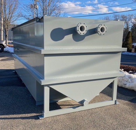
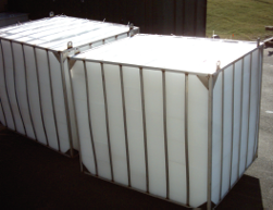
We offer a complete line of high efficiency, stainless steel above ground oil water separators that will remove nearly all free and dispersed non-emulsified oil and settleable solids from the waste stream.
We offer a complete line of high efficiency, stainless steel above ground oil water separators that will remove nearly all free and dispersed non-emulsified oil and settleable solids from the waste stream.
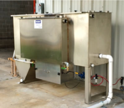
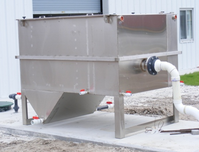
The SPT Series Integrated Pretreatment Systems integrate an oil water separator with a clarifier to remove both floating oils and settlable solids.

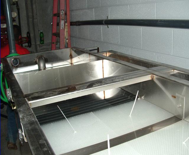
One of the most effective ways to remove floating oils from an oil water separator is with an electric 12” disk skimmer. Mounted on the side of the clarifier and/or coalescing compartments, the skimmer assembly consists of an oleophilic wheel that slowly rotates so that oils and sludge adhere to the wheel’s surface. A spring-loaded blade wipes the oil from surface of the wheel and discharges the oil into a steel trough connected to the oil storage tank.
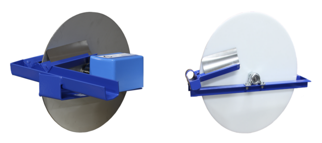
The 115V disk skimmer motor is controlled by a simple control panel with a field-adjustable timer so that you can remove floating oils as often as necessary for your particular application.

OPTIONS AVAILABLE
• Electric or air-driven pump and control systems
• Water polishing packs for strict effluent requirements
• Ozone systems for odor control
• Ozone systems for odor control
• Additional water treatment systems for differing site conditions
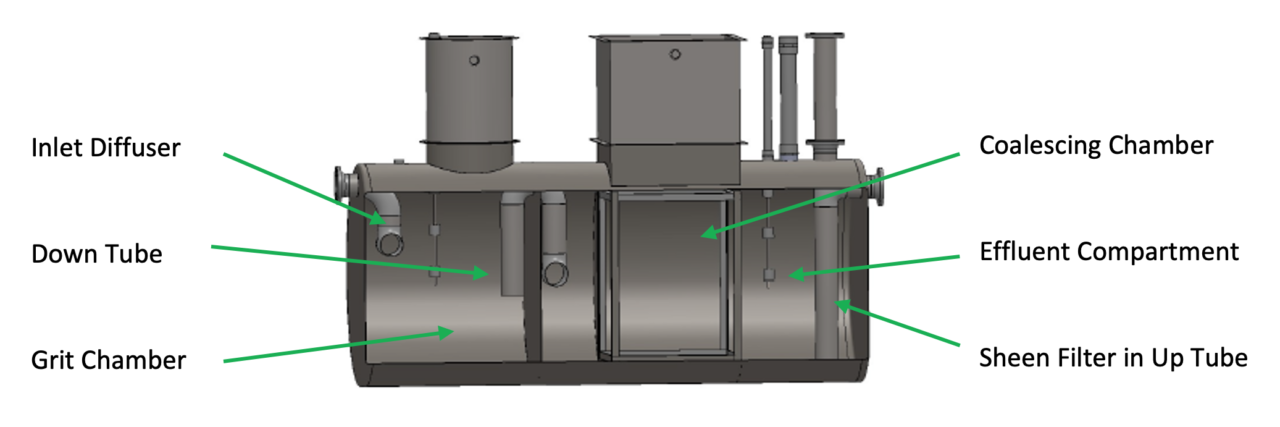
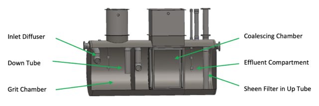
Our new solids settling below ground separator is ideal for any application with high concentration of solids and oil in water.
Most old conventional separators require long retention times, resulting in needlessly large units. They also have little in the way of solids settling. Our new innovative new design has both a much smaller footprint and a much higher removal efficiency for both oil and solids which lowers your total cost of ownership.
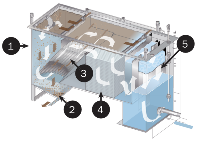
To enhance separation, these separators contain an inlet diffuser, grit chamber/inlet compartment, down tube, coalescing/separation chamber, oil storage area, effluent compartment, and sheen filter.
| Model # | Average Flow Rate (GPM) | Capacity
(Gallons) |
Inlet/Outlet (Inches) | Dimensions, D x L (Feet) |
| WB-QB-35-ES | 35 | 350 | 4 | 3.5 X 6 |
| WB-QB-55-ES | 55 | 550 | 4 | 4 X 6 |
| WB-QB-100-ES | 100 | 1000 | 6 | 4 X 10.75 |
| WB-QB-200-ES | 200 | 2000 | 6 | 5.3 X 12 |
| WB-QB-300-ES | 300 | 2500 | 6 | 5.3 X 15 |
| WB-QB-400-ES | 400 | 3000 | 8 | 5.3 X 18 |
| WB-QB-500-ES | 500 | 3800 | 8 | 6 x 17.5 |
| WB-QB-600-ES | 600 | 4000 | 10 | 6 x 18.75 |
| WB-QB-700-ES | 700 | 7000 | 10 | 8 X 18.67 |
| WB-QB-800-ES | 800 | 7000 | 10 | 8 X 18.67 |
| WB-QB-900-ES | 900 | 7000 | 12 | 8 X 18.67 |
| WB-QB-1000-ES | 1000 | 7500 | 12 | 8 X 20 |
| WB-QB-2000-ES | 1200 | 8500 | 12 | 8 X 22.5 |
| WB-QB-1500-ES | 1500 | 12000 | 16 | 10 X 20.75 |
| WB-QB-2000-ES | 2000 | 14000 | 18 | 10 X 24 |
| WB-QB-2500-ES | 2500 | 17000 | 18 | 10.5 X 26.5 |
| WB-QB-3000-ES | 3000 | 19000 | 20 | 10.5 X 29 |
Call Now to Speak with a Oil Water Separator Specialists – 1-800-453-8639!
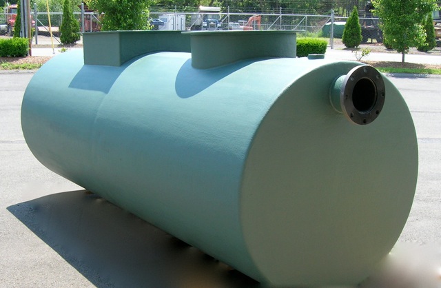
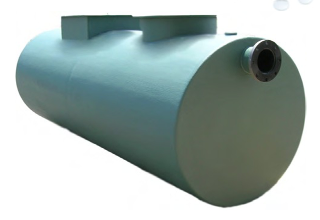
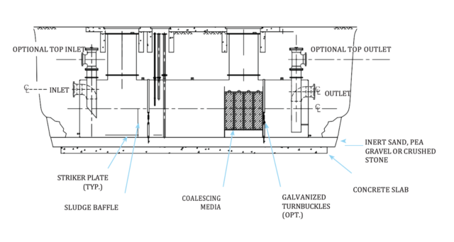
Our single wall or double wall below ground parallel, corrugated plate oil/water separators meet and exceed API 421 requirements, removing essentially 100% of dispersed non-emulsified oil droplets in the waste stream.
These separators are special purpose prefabricated parallel corrugated plate, cylindrical, gravity displacement oil water separators, containing an inlet compartment, sludge chamber, separation chamber, oil storage area and clean water compartment.
As shown below, the separation process if fairly simple. Wastewater flows into the inlet compartment. A baffle interrupts the flow and allows solids to drop out. Next the oil water moves into the separation chamber where our innovative media causes small oil droplets entrained in the water to coalesce into larger ones which then separate from the water and float to the surface. The clean water then travels into the clean water compartment through the outlet to the sewer.
Features

Options
Applications
With these separators, we can provide analysis, which indicates that the separator will be provided with the required square feet of projected plate separation area to achieve the specified performance under laminar flow (i.e. Reynolds Number of less than 500) conditions. This service can include calculations signed by a registered professional engineer.
| Underground Oil Water Separator Specifications | |||
| Model # | Average Flow Rate (GPM) | Capacity (GALLONS) | Dimensions, D x L (FT) |
| WB-QB-342 | 35 | 350 | 3.5 x 6 |
| WB-QB-548 | 55 | 550 | 4 x 6 |
| WB-QB-1048 | 100 | 1000 | 4 x 10.75 |
| WB-QB-2064 | 200 | 2000 | 5.3 x 12 |
| WB-QB-3064 | 300 | 3000 | 5.3 x 18 |
| WB-QB-4064 | 400 | 4000 | 5.3 x 24 |
| Larger sizes available. | |||
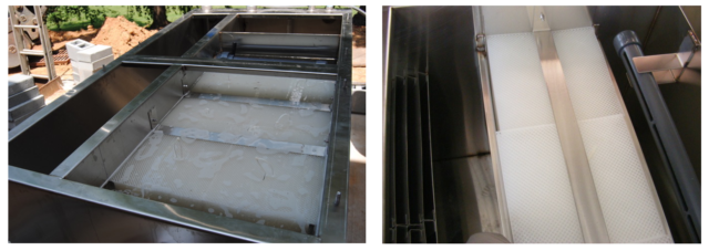
Our standard media has vastly superior properties compared to the traditional media used in oil-water separators. These properties result in a more efficient and effective separation than that attained by traditional coalescing media.
Give us a call at 800-453- 8639 for more information!

Even though the terms “Oil Interceptors” and “Oil Water Separators” are often used
interchangeably, they are very different systems.
Oil interceptors are typically used in low flow drain lines where small quantities of oils, sediment
and other liquid contaminants can be “intercepted”. These drain lines may come from variety of
facilities including covered parking garages, machine shops, service stations, and manufacturing
facilities.
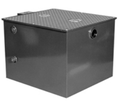
Usually constructed of steel, fiberglass or plastic, interceptors are simple systems which include a
baffle plate, a solids bucket, and a separation area. As the water enters the interceptor, a baffle
plate reduces the flow and turbulence of the incoming water which helps to drop out some solids
and sludge.
A low flow rate and little turbulence permits the oils and other light density to slowly separate from
the water and rise to the top of the separation area. From there, relatively oil-free water is
discharged to the sewer.
 In comparison, Oil Water Separators have a far more sophisticated and efficient design. They are used in higher volume applications such as industrial wash operations, parking lots, re-fueling facilities and military installations where there is a potential for a much higher volume of water, oil, and contaminants.
The standard oil water separator is a steel or stainless steel tank containing an inlet compartment, baffles system, sludge chamber, separation chamber with coalescing media, and clean water outlet chamber.
 The water enters the inlet compartment where the oil separation process begins. Here, baffles slow down the water flow which causes some of the solids to drop out of suspension. Next, parallel corrugated coalescing media in the separation chamber cause the oil droplets in the water to coalesce together, and increase in size until they separate from the water. This coalescing media, with an internal structure of interconnecting channels, can remove essentially all free and dispersed, non-emulsified oils to an effluent concentration of less than 5 ppm – which is acceptable for discharge to most municipal sewer systems.
WashBaySolutions.com offers a full line of oil and water separators that conform to the guidelines of API 421 for the removal of all free and dispersed non-emulsified oil and solids that settle from the waste stream. Get a Quote Today!
Please see a list of question and answers below related to our oil water separator products.

Problem: A car dealer moving into a new facility with a limited time lease. The property owner did not want them to cut concrete or substantially alter the property but the dealer needed to be able to wash dozens of cars per week onsite, contain the water and discharge it properly to the sewer.
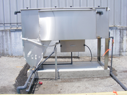
Solution: For a complete wash system, we recommended installing a SPT-10 Clarifier Oil Water Separator System, a cold water pressure washer with a portable hose reel, and a portable wash containment pad. This allows them to wash as many cars as possible without any major modifications to the property. They will also be able to move the entire system to a new facility at the end of their lease. With their input, we helped them layout the system to maximize their space.
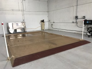
After installation of the pad, however, they noticed the concrete floor slope much slighter than originally thought and that the wash water was not moving off the pad well. This flat slope left his staff working in standing water and the SPT-10 not being able to process the wash water properly.
To improve this drainage issue, our staff developed a low cost under layer for the wash pad which created a slight slope for the water. We then installed this under layer and re-piped the in-take piping for the SPT-10 so the wash water flows freely. The general manager of the facility is very pleased with our systems and service.
North CarolinaHeadquarters
At WashBaySolutions.com, we have been specializing in high tech, custom-engineered solutions to complex washing and wastewater issues since 1991.WashbaySolutions.comsales@washbaysolutions.comLOCATIONSWashBay Solutions International