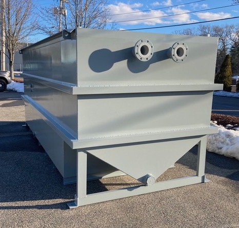
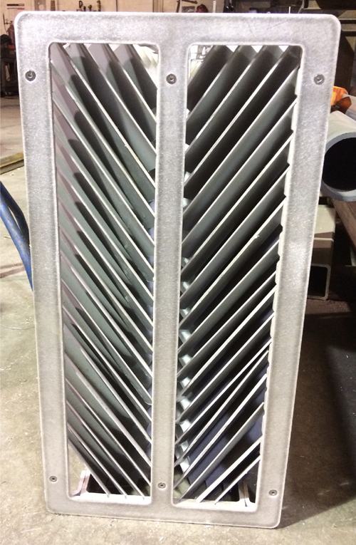
We offer a complete line of high efficiency, stainless steel above ground oil water separators that will remove nearly all free and dispersed non-emulsified oil and settleable solids from the waste stream.
We offer a complete line of high efficiency, stainless steel above ground oil water separators that will remove nearly all free and dispersed non-emulsified oil and settleable solids from the waste stream.
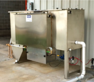
The SPT Series Integrated Pretreatment Systems integrate an oil water separator with a clarifier to remove both floating oils and settlable solids.

One of the most effective ways to remove floating oils from an oil water separator is with an electric 12” disk skimmer. Mounted on the side of the clarifier and/or coalescing compartments, the skimmer assembly consists of an oleophilic wheel that slowly rotates so that oils and sludge adhere to the wheel’s surface. A spring-loaded blade wipes the oil from surface of the wheel and discharges the oil into a steel trough connected to the oil storage tank.
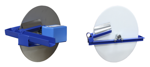
The 115V disk skimmer motor is controlled by a simple control panel with a field-adjustable timer so that you can remove floating oils as often as necessary for your particular application.

OPTIONS AVAILABLE
• Electric or air-driven pump and control systems
• Water polishing packs for strict effluent requirements
• Ozone systems for odor control
• Ozone systems for odor control
• Additional water treatment systems for differing site conditions
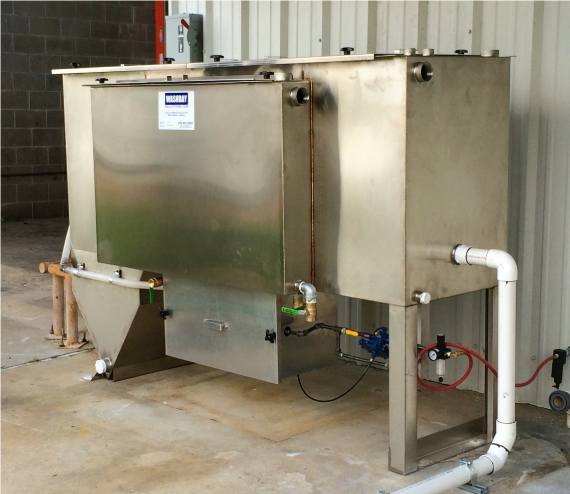
FABRICATION: The clarifier/separator is a special purpose prefabricated inclined plate and parallel corrugated plate, rectangular, gravity displacement, type unit. The clarifier/separator shall be comprised of a tank containing an inlet compartment, sludge chamber, a separation compartment, and clean water outlet chamber.
TANK: The tank shall be a single wall construction of 11 gauge stainless steel conforming to ASTM A240, type 304 stainless steel. Welding will be in accordance with AWS D1.1 to provide a watertight tank that will not warp or deform under load.
PIPE CONNECTIONS: All pipe connections 3” and smaller are FNPT couplings. All connections 4“ and larger are flat face flanges with ANSI 150 pound standard bolt circle.
LIFTING LUGS: The tank shall be provided with properly sized lifting lugs for handling and installation.
COVERS: The tank will be provided with vapor tight covers for vapor control. Gas vents and suitable access openings to each compartment will be provided. The covers shall be constructed of marine grade aluminum and will be fastened in place. A gasket shall be provided for vapor tightness. 3/8-16 bolts and threaded knobs will be provided for cover attachment.
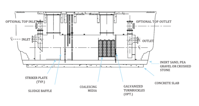
INLET COMPARTMENT & INCLINED PLATES: The inlet chamber shall be comprised of a non-clog diffuser to distribute the flow across the width of the chamber. The inlet compartment shall be of sufficient volume to effectively reduce influent suspended solids, dissipate energy and begin separation. The inclined plates will sit elevated on top of a sludge chamber. As the water moves upwards the suspended particles have their upwards velocity interrupted by the inclined plates. These particles drop down and slide down the inclined plate and join larger previously settled particles in sludge hopper. The sludge compartment will be provided to retain settleable solids.
SEPARATION CHAMBER: The oil separation chamber shall contain HD Q-PAC Coalescing Media containing a minimum of 132 square feet per cubic foot of effective coalescing surface area. The medias needle like elements (plates) shall be at 90 degrees to the horizontal or longitudinal axis of the separator. Spacing between these elements shall be spaced 3/16” apart for the removal of a minimum of 99.9% of free droplets 20 micron in size or greater. The elements are positioned to create an angle of repose of 90 degrees to facilitate the removal of solids that may tend to build up on the coalescing surfaces, which would increase velocities to the point of discharging an unacceptable effluent.
Laminar flow with a Reynolds Number of less than 500 at a maximum designed flow rate shall be maintained throughout the separator packed bed including entrance and exit so as to prevent re-entrainment of oils with water. Flow through the polypropylene coalescing media shall be crossflow perpendicular to the vertical media elements such that all 132 square feet/cubic foot of coalescing media is available for contact with the coalescing surfaces.
None of the coalescing media surfaces shall be pointing upward so as not to be available for contact with the cross-flowing oily water. The media shall have a minimum of 87% void volume to facilitate sludge and dirt particles as they fall off the vertical elements and settle in the sludge compartment. The media when installed in crossflow OWS shall meet US EPA Method 413.2 and also European Standard 858-1.
BAFFLES: The tank shall be provided with an oil retention & underflow weir, and overflow weir. The underflow weir will be positioned to prevent re-suspension of settled solids.
SLUDGE CHAMBER: The sludge chamber shall be located prior to the coalescing compartment for the settling of any solids. It shall also prevent any solids from entering the clean water chamber.
OIL SKIMMER: The clarifier compartment and the oil separation compartment will be provided with rotatable pipe skimmers for gravity decanting of the separated oil to a product storage tank.
CLEAN WATER CHAMBER: The tank will be provided with a clean water chamber which allows the water to leave the separator by pumped flow through the clean water outlet port.
VENTS: 2″ vents will be provided for vent piping to atmosphere.
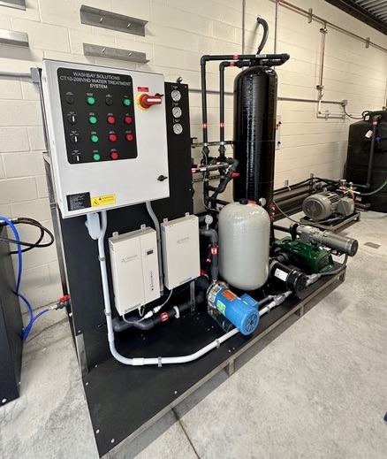
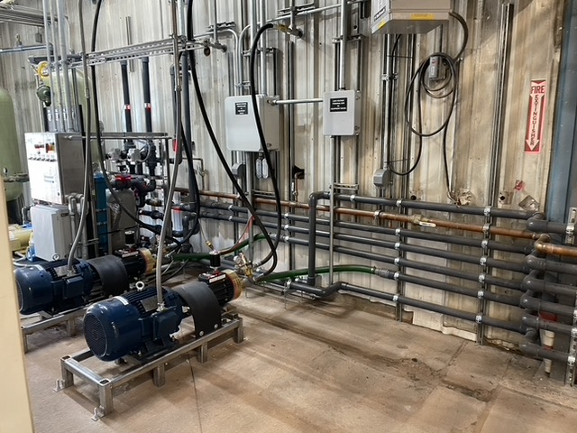
PUMP TRANSFER SYSTEM: The system is provided with either an electric powered or air-powered diaphragm transfer pump. Electric motor can be 110V/240V/480V. Pump is installed near the SPT system. A screen should be placed on the pump intake to reduce the amount of solids entering the system.
PUMP CONTROL PANEL: The control panel for the pump will be housed in a NEMA-4X enclosure. The controls may include a Main Disconnect Switch, an Emergency Stop switch, a Manual/off/auto pump switch, 24-volt control relay, Circuit Breaker, motor contactor and overload, and Green run, red fault panel lights. It may be UL certified, if needed.
OPTIONAL POLISHING PACK: A final water polishing pack with a stainless steel flow dissipator plate and oil absorbent bags may be provided with the system if local municipalities have sewer effluent requirements.
OPTIONAL OZONE SYSTEM: The system may be provided with an ozone generator to reduce odors.
| SPT-10 | SPT-20 | SPT-30 | SPT-50 | SPT-75 | SPT-100 | |
| Flow Rate | 1-10 GPM | 1-20 GPM | 1-30 GPM | 1-50 GPM | 1-75 GPM | 1-100 GPM |
| Tank Capacity | 300 Gal | 652 Gal | 645 Gal | 968 Gal | 1419 Gal | 1931 Gal |
| Sludge Volume | 27 Gal | 27 Gal | 45 Gal | 85 Gal | 85 Gal | 85 Gal |
| Ozone Generation | Optional | Optional | Optional | Optional | Optional | Optional |
| Product Tank | 40 Gal | 40 Gal | 40 Gal | 75 Gal | 75 Gal | 75 Gal |
| Polishing Pack | Optional | Optional | Optional | Optional | Optional | Optional |
| Approx. dimensions, FT | 3’W x 8’L x 5’H | 4’W x 8.5’L x 6’H | 4’W x 9’L x 6’H | 4’W x 9.75’L x 6’H | 4.5’W x 10’L x 7’H | 5.3’W x 10.5’L x 7.3’H |
| Construction | Stainless Steel | Stainless Steel | Stainless Steel | Stainless Steel | Stainless Steel | Stainless Steel |
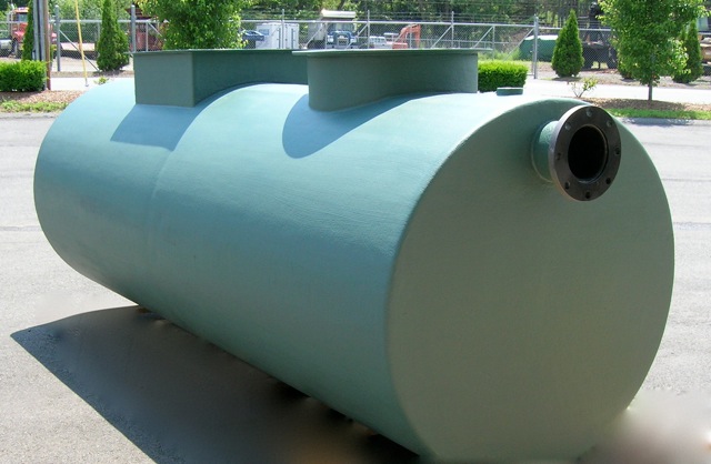
Our single wall or double wall below ground parallel, corrugated plate oil/water separators meet and exceed API 421 requirements, removing essentially 100% of dispersed non-emulsified oil droplets in the waste stream.
These separators are special purpose prefabricated parallel corrugated plate, cylindrical, gravity displacement oil water separators, containing an inlet compartment, sludge chamber, separation chamber, oil storage area and clean water compartment.
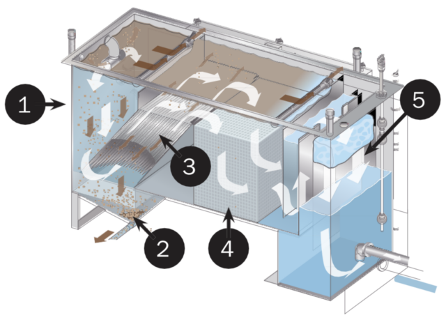
As shown below, the separation process if fairly simple. Wastewater flows into the inlet compartment. A baffle interrupts the flow and allows solids to drop out. Next the oil water moves into the separation chamber where our innovative media causes small oil droplets entrained in the water to coalesce into larger ones which then separate from the water and float to the surface. The clean water then travels into the clean water compartment through the outlet to the sewer.
Features

Options
Applications
With these separators, we can provide analysis, which indicates that the separator will be provided with the required square feet of projected plate separation area to achieve the specified performance under laminar flow (i.e. Reynolds Number of less than 500) conditions. This service can include calculations signed by a registered professional engineer.
| Underground Oil Water Separator Specifications | |||
| Model # | Average Flow Rate (GPM) | Capacity (GALLONS) | Dimensions, D x L (FT) |
| WB-QB-342 | 35 | 350 | 3.5 x 6 |
| WB-QB-548 | 55 | 550 | 4 x 6 |
| WB-QB-1048 | 100 | 1000 | 4 x 10.75 |
| WB-QB-2064 | 200 | 2000 | 5.3 x 12 |
| WB-QB-3064 | 300 | 3000 | 5.3 x 18 |
| WB-QB-4064 | 400 | 4000 | 5.3 x 24 |
| Larger sizes available. | |||
In some applications with extensive contamination, a simple oil water separator is simply not enough to treat the water prior to sewer discharge. Our heavy-duty MM-Series treatment systems treat wash water in multiple stages so it can be safely discharged to the sewer or, in many cases, the surroundings.
Almost all commercial washing operations produce some solids so the first stage of our filtration process is the solids handling system. We help you develop site-specific solutions to eliminate as many solids as possible before running the water through to the next stage of filtration. Solutions include custom-designed sumps, basins, trenches or screening systems.
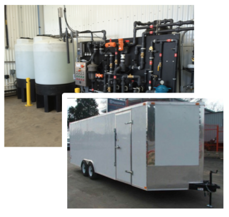
After the coarse solids settling, the water is processed through either a multi-compartment stainless steel oil water separator or a stainless steel clarifier oil-water separator, which separates out smaller suspended solids, oil and water. In the first compartment of the clarifier oil water separator, free oils float to the surface. In the second section, the stainless steel clarifying plates remove coarse amounts of oil from the waste stream and remove as much Total Suspended Solids (TSS) as possible. The angles of the non-clogging plates are 55° which will allow any solids to slide down the plates into the solids hopper, where they can easily be pumped out. Finally, the coalescing media removes essentially 100% of all free and dispersed non-emulsified oils so the FOG effluent concentration can be as low as 5 ppm.
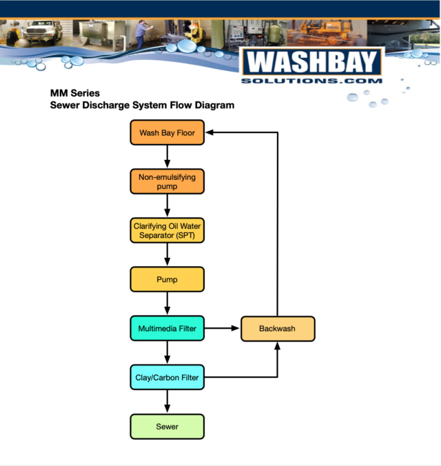
After the clarifier oil-water separator, the water is pumped though a multi-media (sand, gravel, anthracite) filter and then safely discharged to the sewer or surroundings. Processed water passing through the system will be free of substantially all emulsified oils, waxes and other volatile organic compounds with only limited soaps and detergents remaining in the treated water. If needed, a blended activated carbon or a carbon/clay mixture tailored to a particular waste stream can be added as an optional polishing filter.
Depending on the location, many options are available to maximize the efficiency of the wastewater treatment system including:
|
MODEL |
MM-10/10 |
MM-35/20 |
MM-65/50 |
MM-100* |
|
DESIGN FLOW RATE, GPM |
1-10 |
1-25 |
10-55 |
30-100 |
|
COALESCING PLATE AREA, SF |
41 |
124 |
211 |
400 |
|
COALESCING MEDIA, CF |
4 |
8 |
24 |
48 |
|
CLARIFIER SEPARATOR SIZE, FT (WxLxH) |
3 x 7 x 5 |
3.5 x 8 x 6 |
4 x 10 x 6 |
5 x 11 x 7 |
|
NON-EMUSIFYING INFLUENT PUMP, GPM MAX |
20 |
50 |
75 |
125 |
|
MULTI-MEDIA, LBS |
300-500 |
500-1000 |
2500-2600 |
3700-4200 |
|
OPTIONAL POLISHING CLAY/CARBON, CF |
4-15 |
10-40 |
20-40 |
40 |
|
FILTER PUMP, HP |
1.5 |
2 |
3 |
5 |
|
DIRTY WATER STORAGE VOLUME, GAL |
500-750 |
500-1000 |
750-1000 |
1000-1500 |
|
CONTROL SYSTEM |
PLC, Automatic, Manual or Off |
|||
|
PUMP FRAME SIZE, FT (WxLxH) |
3 x 6 x 6.5 |
3 x 8 x 8 |
||
|
POWER REQUIREMENTS |
208 / 240 V 1 ph or 208 / 240 / 480 V 3 ph |
|||
* LARGER CAPACITY SYSTEMS (200-1500 GPM) ARE AVAILABLE
We have developed a revolutionary heavy-duty wash and treatment system by integrating our demucking system with our clarifier oil water separator system.
Using low flow pumps, moderate pressure and specialized nozzles, our robustly- designed demucker systems can quickly clean large trucks, tracked vehicles or any heavy equipment caked with mud, clay, ice, or muck – using only 20 gpm of water.
After washing, we can then process this water through our stainless steel clarifier oil water separator to reduce your environmental liabilities. Even though full of solids, oils and grease, our separator will effectively treat this wash water for re-use or discharge.
Fast and effective cleaning with low water treatment costs – definitely a win-win situation!
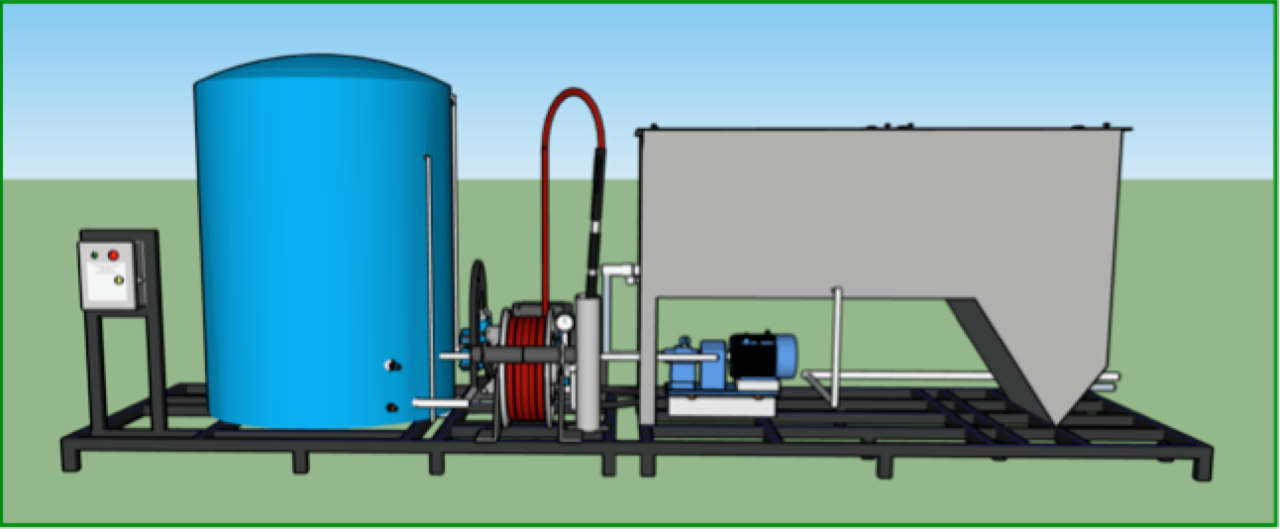
Reduce your environmental liabilities and get the power of a wash monitor with a fraction of the water usage!
|
Pumping System |
DTS-20 |
|
Max Flow Rate & Pressure |
20 GPM @ 850 PSI |
|
Uses Fresh or Recycled Water |
Both |
|
Motor, HP |
15 |
|
Pump Type |
Electric Diaphragm |
|
Controls |
Manual/Remote/PLC |
|
Hose |
50-75’ L @ ¾” D |
|
Gun/Wand |
Handheld Stream-to-Cone |
|
Water Storage |
500 Gallon Poly Tank |
|
Industrial Grade Hose Reel |
Manual, Spring Rewind, Portable |
|
Electric |
120/208/480/575 V 3 PH 50/60 HZ |
|
Approximate Dimensions (with tank) |
8’ L x 4’ W x 7’ H |
|
|
|
|
Clarifier Oil Water Separator |
|
|
Max Flow Rate |
20 GPM |
|
Internal Tank Capacity |
650 Gallons |
|
Sludge Capacity |
27 Gallons |
|
Coalescing Media |
6 Cubic Feet |
|
Pump Type |
Air or Electric Diaphragm |
|
Controls |
Air or Electric Manual/Remote/PLC |
|
Air/Electric |
8-14 cfm at 40 psi/120/208/480/575 V 3 PH 50/60 HZ |
|
Approximate Dimensions |
8’ L x 3’ 6” W x 6’ H |
“I also want to let you know how impressed I was with all of the JDI equipment. Every piece of equipment you provided was exceptionally well constructed. I am thoroughly impressed with everything!”
“Everything I have seen and heard so far indicates that they are very happy with the demuckers. They are even creeping into the building and washing trucks every chance they get as ‘trial runs’, even before the contractor has officially turned the project over to them.” – Brian S.

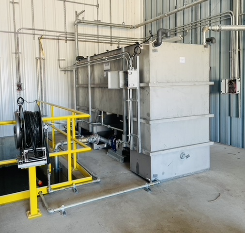
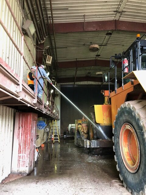
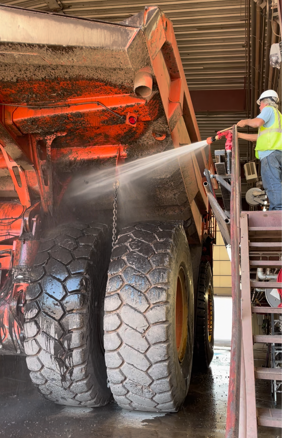
Issues: A very large mining operation was rehabbing its existing wash pad and adding a new one. As with most mining operations, most of their vehicles are very large and, therefore, can carry a large amount of solids into the wash bay. These solids get caked into every surface of the vehicles.
The engineers designing their new building contacted us to assist with washing and treatment equipment and maximize their wash bay design.
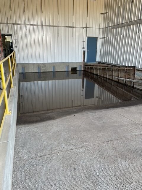
Solution: We worked closely with their engineers to first design a very efficient solids handling and settling system consisting of trenches, sumps and a settling basin.
Once we completed the design, we recommended a number of washing systems to augment their pressure washing systems. Due to the fact that they had a variety of vehicles and equipment, they decided on dual 20 GPM @ 1000 psi demucking systems, an undercarriage wash and monitor system for washing. One demucking will be used also be used to supply the undercarriage wash system.
For their application, we also developed a very effective cleaning system which included multiple compact water monitors placed strategically in the wash bay. Each monitor system will supply 100 gpm @ 100 psi. For easy movement, the wash monitors are attached to custom steel trollies that are mounted on steel rails inside the wash bay. It can be easily customized with a wide range of nozzles selections.
Since they would be washing in different wash areas, we then coordinated with the electrical engineers to integrate all of the remote controls so the systems could be easily controlled by a small crew.
After washing, the water is treated so that it can be re-used by a complete self-contained system, capable of processing 100 gpm. It is a Closed Loop Carbon Treatment System so there is zero fluid discharge to the facilities’ surroundings. The system includes a clarifier oil water separator to remove oils, ozone to remove odors and multi-level filtration to remove of particles greater than 10 microns in size, substantially all emulsified oils, waxes and other volatile organic compounds.
All of the systems were easily upgraded to meet mine safety standards.
In many washing applications, huge volumes of solids are generated during the washing process. This is especially true in the construction and mining industries. Some of the heavier solids drop out of suspension quickly while others get entrained in the oily wastewater.
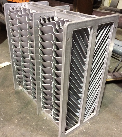
To insure our oil water separators do not clog in these high solids washing applications, we have developed a new corrugated plate coalescing media with a cross-flow design.
This new media design is a series of plates curved in a simple wave shape. As the water enters the separator, the flow is directed evenly across the surface of the media plates. The solids are captured and fall to the trough area of the corrugated plates below and the oils rise and stick to the trough area of the plates above.
The separator design maintains laminar flow throughout the media so the oil and solids do not remix. Separated oil flows upwards along the plates to the top of the separator where it can be removed and solids slide down the smooth corrugated plates to the hopper area where they can be easily removed.
By coupling high efficiency separation with easy maintenance of this new media, you will ensure your oil water separator operates at peak performance in high solids applications.
Give us a call at 800-453- 8639 for more information!
North CarolinaHeadquarters
At WashBaySolutions.com, we have been specializing in high tech, custom-engineered solutions to complex washing and wastewater issues since 1991.WashbaySolutions.comsales@washbaysolutions.comLOCATIONSWashBay Solutions International