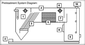
[Diagram Details Below]
- Stainless Steel Inlet Compartment – The water is pumped into the system through a non-clogging diffuser pipe to distribute the flow. The inlet chamber is designed to reduce suspended solids, dissipate energy and begin separation.
- Sump Pump – Water is pumped into the system via an air diaphragm sump pump.
- Inclined Plates – Inclined plates above the sludge chamber catch suspended particles as the water stream moves into the separation chamber.
- Separation Chamber – After the water travels up the inclined plates, it flows into the stainless steel separation chamber containing the coalescing media.
- Coalescing Media Packs – The high efficient coalescing pack in the separation chamber further slow the water velocity so oil drops out of suspension and clings to the media. This media will remove 99% of free oil droplets 20 microns or larger.
- Oil Skimmer – The oil that has dropped out of suspension is then skimmed off the top of the separation chamber and into a tank for easy removal.
- Baffles – An underflow weir will prevent re-suspension of solids while an oil retention weir will keep the oil in the separation compartment.
- Ozone Generator – The water is injected with ozone to kill odor-causing bacteria.
- Clean Water Chamber – The third stage is a clean water chamber where the clean water will flow out for reuse to the drain.
- Float Control System – SPT Series Systems come with optional control systems for simple, automatic operation.