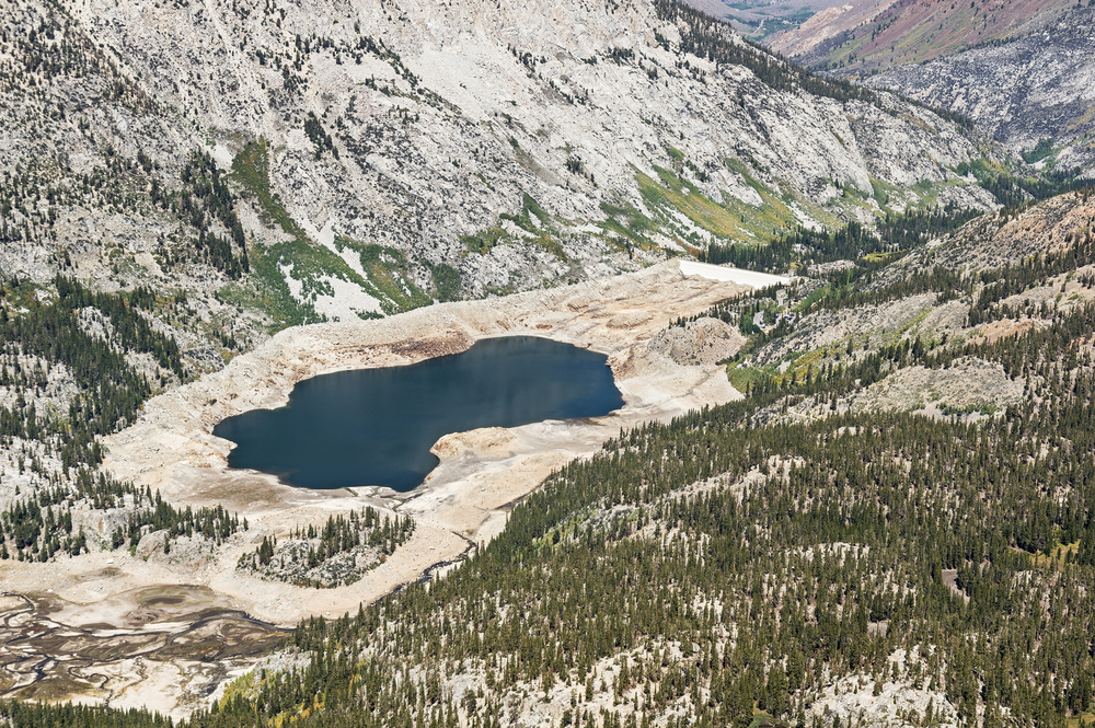
California is now entering its fourth year of drought. State and local authorities have asked residents to voluntarily reduce water use by 20%. Various water managers estimate that available water will last for a year or at the most three.
While at present the authorities have asked for a voluntary reduction in water use, this is likely to be followed soon by price rationing where households that consume more than 150 gallons of water a day will be charged a higher rate. Apart from residents, industries and businesses too have to work to reduce water usage to help overcome the drought and reduce their water bills or keep them under manageable levels.
Recycling Waste Water
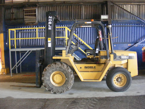
One of the most effective ways of reducing water consumption is by recycling waste water. This helps reduce effluent discharge and ensures that the same water is reused. Many industries such as trucking, fork lift operators, rail operators, car wash units, and others use water for washing the vehicles. This is part of maintenance and ensures a professional image, happy and health drivers, and clean transportation facilities. However, the amount of water used can be high. By recycling the waste water, the businesses can reduce their water consumption and their water bills.
CT Series Wash Water Systems
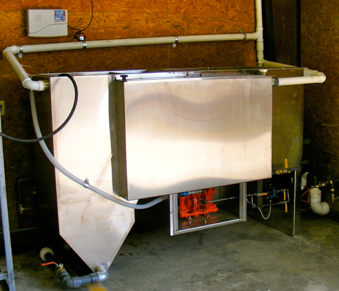
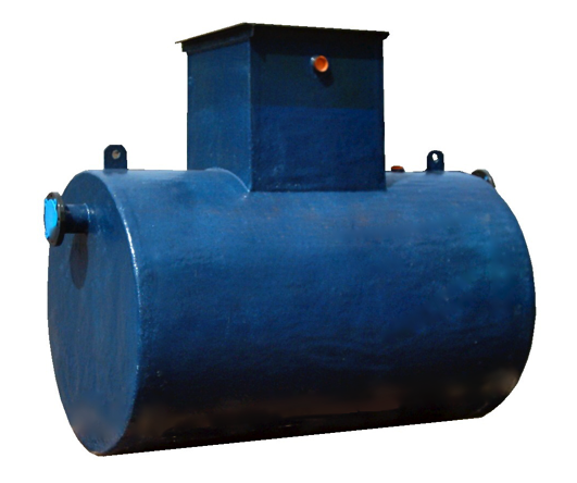
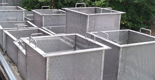
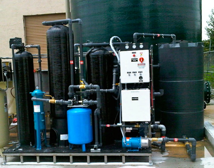
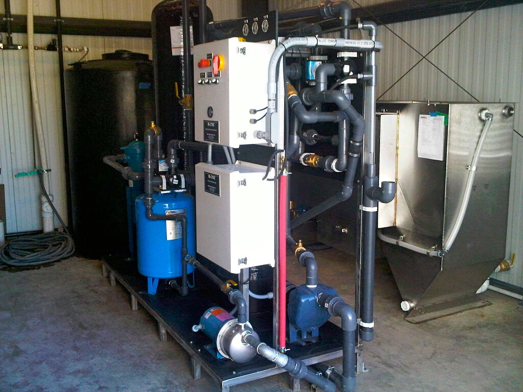
Commercial trucking companies can install the CT Series wash water systems to recycle and reuse the waste water. The system removes settle-able solids and non-emulsified oil droplets before filtering the water to make it reusable. The multi-stage reclaim and discharge process begins with a solid removal process. This system can be designed to be “site specific” – taking into account the specific features of the site.
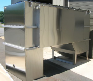
A stainless steel oil and water separation system is used to remove non emulsified oil drops from the water as well as settle-able solids. Once this is done, the water is passed through a highly efficient water filtration process that uses corona and activated carbon to purify the water. This removes all contaminants that are larger than 10 microns in size including volatile organic compounds, waxes, and oils.
RL Series Treatment Systems
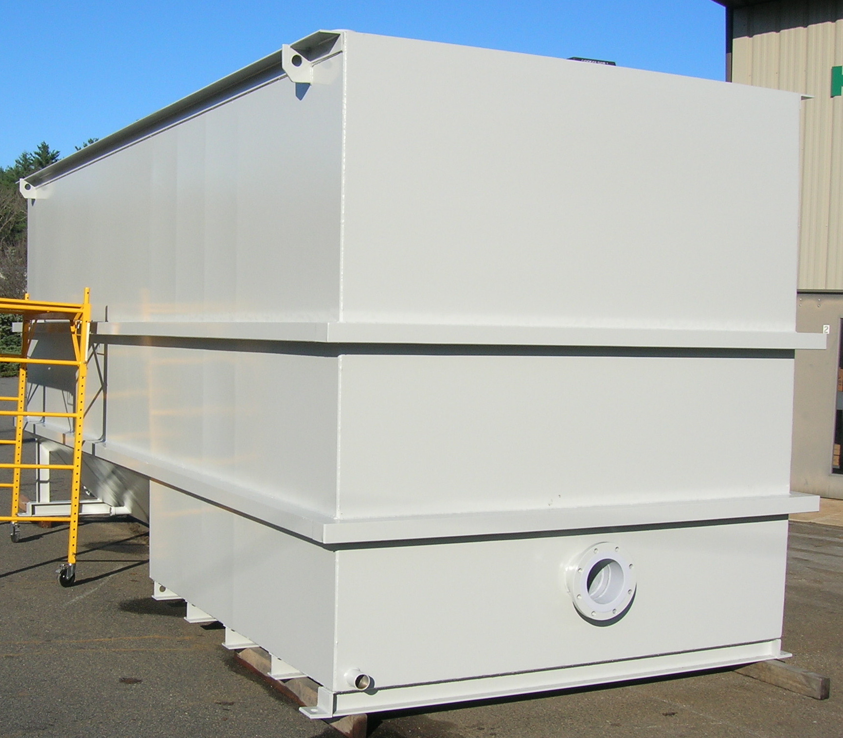
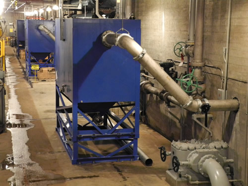
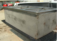
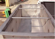
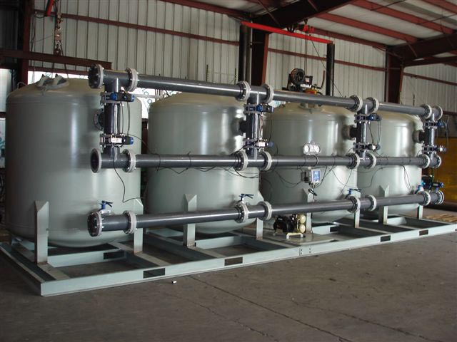
Another efficient method of transportation is by rail. A rail company that wants to reduce its water usage and still keep its carriages clean can do so by installing the RL Series Treatment Systems. These systems have been developed especially for the railways. They can be combined with existing rail wash systems to ensure that the water use is significantly reduced.
First, the wash water is passed through a stainless steel clarifier oil water separator that removes settle-able solids, and separates the oil and water. All suspended solids are removed at this stage as well as free and dispersed non emulsified oil. Next, the water is passed through a solids filtration system that uses blended activated carbon. This process will remove waxes, volatile organic compounds, and all particles greater than 10 microns in size, ensuring water that can be reused for washing the railway carriages.


 TREATMENT SYSTEMS")