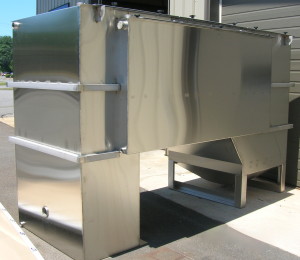
We offer a complete line of high efficiency, stainless steel above ground oil water separators that will remove nearly all free and dispersed non-emulsified oil and settleable solids from the waste stream.
We offer a complete line of high efficiency, stainless steel above ground oil water separators that will remove nearly all free and dispersed non-emulsified oil and settleable solids from the waste stream.
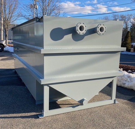
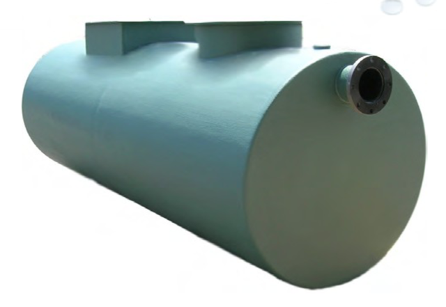
Our new solids settling below ground separator is ideal for any application with high concentration of solids and oil in water.
Most old conventional separators require long retention times, resulting in needlessly large units. They also have little in the way of solids settling. Our new innovative new design has both a much smaller footprint and a much higher removal efficiency for both oil and solids which lowers your total cost of ownership.
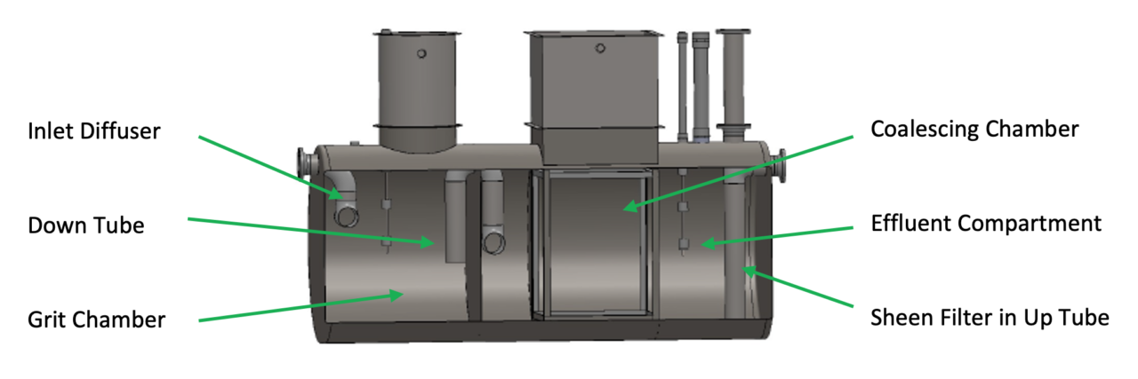
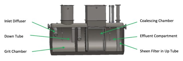
To enhance separation, these separators contain an inlet diffuser, grit chamber/inlet compartment, down tube, coalescing/separation chamber, oil storage area, effluent compartment, and sheen filter.
| Model # | Average Flow Rate (GPM) | Capacity
(Gallons) |
Inlet/Outlet (Inches) | Dimensions, D x L (Feet) |
| WB-QB-35-ES | 35 | 350 | 4 | 3.5 X 6 |
| WB-QB-55-ES | 55 | 550 | 4 | 4 X 6 |
| WB-QB-100-ES | 100 | 1000 | 6 | 4 X 10.75 |
| WB-QB-200-ES | 200 | 2000 | 6 | 5.3 X 12 |
| WB-QB-300-ES | 300 | 2500 | 6 | 5.3 X 15 |
| WB-QB-400-ES | 400 | 3000 | 8 | 5.3 X 18 |
| WB-QB-500-ES | 500 | 3800 | 8 | 6 x 17.5 |
| WB-QB-600-ES | 600 | 4000 | 10 | 6 x 18.75 |
| WB-QB-700-ES | 700 | 7000 | 10 | 8 X 18.67 |
| WB-QB-800-ES | 800 | 7000 | 10 | 8 X 18.67 |
| WB-QB-900-ES | 900 | 7000 | 12 | 8 X 18.67 |
| WB-QB-1000-ES | 1000 | 7500 | 12 | 8 X 20 |
| WB-QB-2000-ES | 1200 | 8500 | 12 | 8 X 22.5 |
| WB-QB-1500-ES | 1500 | 12000 | 16 | 10 X 20.75 |
| WB-QB-2000-ES | 2000 | 14000 | 18 | 10 X 24 |
| WB-QB-2500-ES | 2500 | 17000 | 18 | 10.5 X 26.5 |
| WB-QB-3000-ES | 3000 | 19000 | 20 | 10.5 X 29 |
Call Now to Speak with a Oil Water Separator Specialists – 1-800-453-8639!
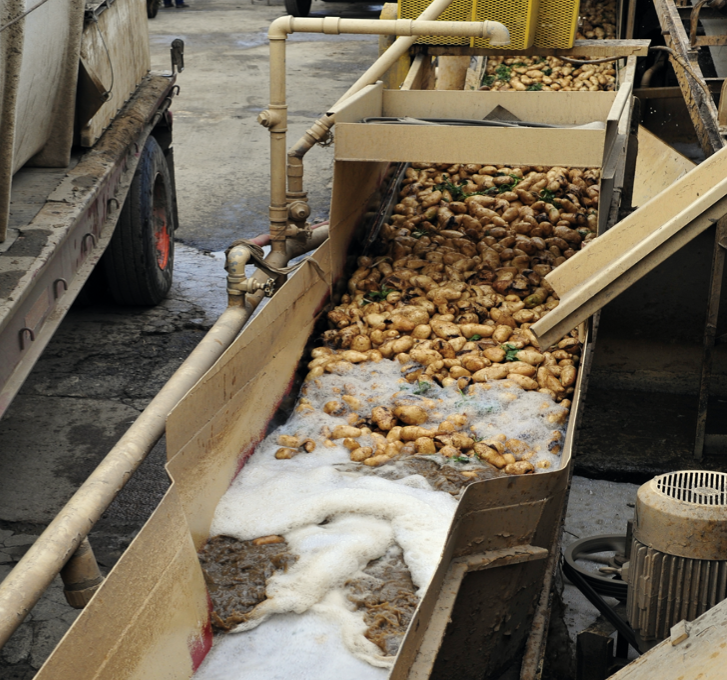
Food processing procedures are as varied as the food produced! The processing and packaging procedures for spaghetti sauce are a lot different from those of sausage, cheese and bread. And, each process produces their own unique waste streams.
That’s where we come in. We can work with your staff and custom-design a comprehensive washing and water treatment system based on your needs.
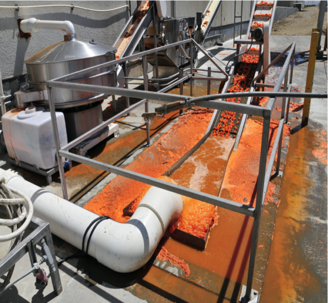
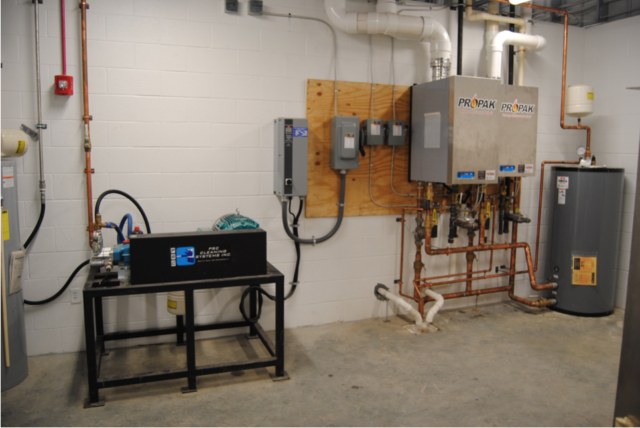
If you have to wash machinery, piping, conveyors, shelving or tanks, we can help you with pumping and heater packages featuring manual, automated and Variable Frequency Drive controls. A Variable Frequency Drive (VFD) system is one of the most cost effective units to run and maintain and allows multiple users at the same time. Different heating packages can be paired with the pumping and pressure washing systems so that you get the proper water temperature for your washing operation. Foaming, chemical injection and ozone disinfection systems can also be added to the washing systems, if required.
 We can help you treat the wash water so that it can be properly discharged. If the washing process produces solids, we have a range of solutions to first separate the solids from the wastewater. After the solids are removed, we can process the water through our wastewater treatment systems.
We provide the following equipment:
If you are in the food industry and need a washing and water treatment solution, give us a call now at 800-453-8639!
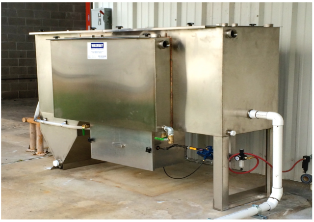

New SOWS Systems Remove Both Free & Dispersed Oil AND Settable & Suspended Solids!
Introducing the new Best Available Technology (BAT) for the treatment of produced water and flow-back water. The Solids and Oil Water Separation Systems (SOWS) are horizontal gravity flow treatment systems designed to separate settleable solids, suspended solids, and free and dispersed oil.
This system is a significant improvement to the currently used CPI Separators which can only separate free oil and settleable solids – allowing a considerable amount of dispersed oil, suspended solids, and stable emulsions to pass through the system.
Applications:
Benefits:
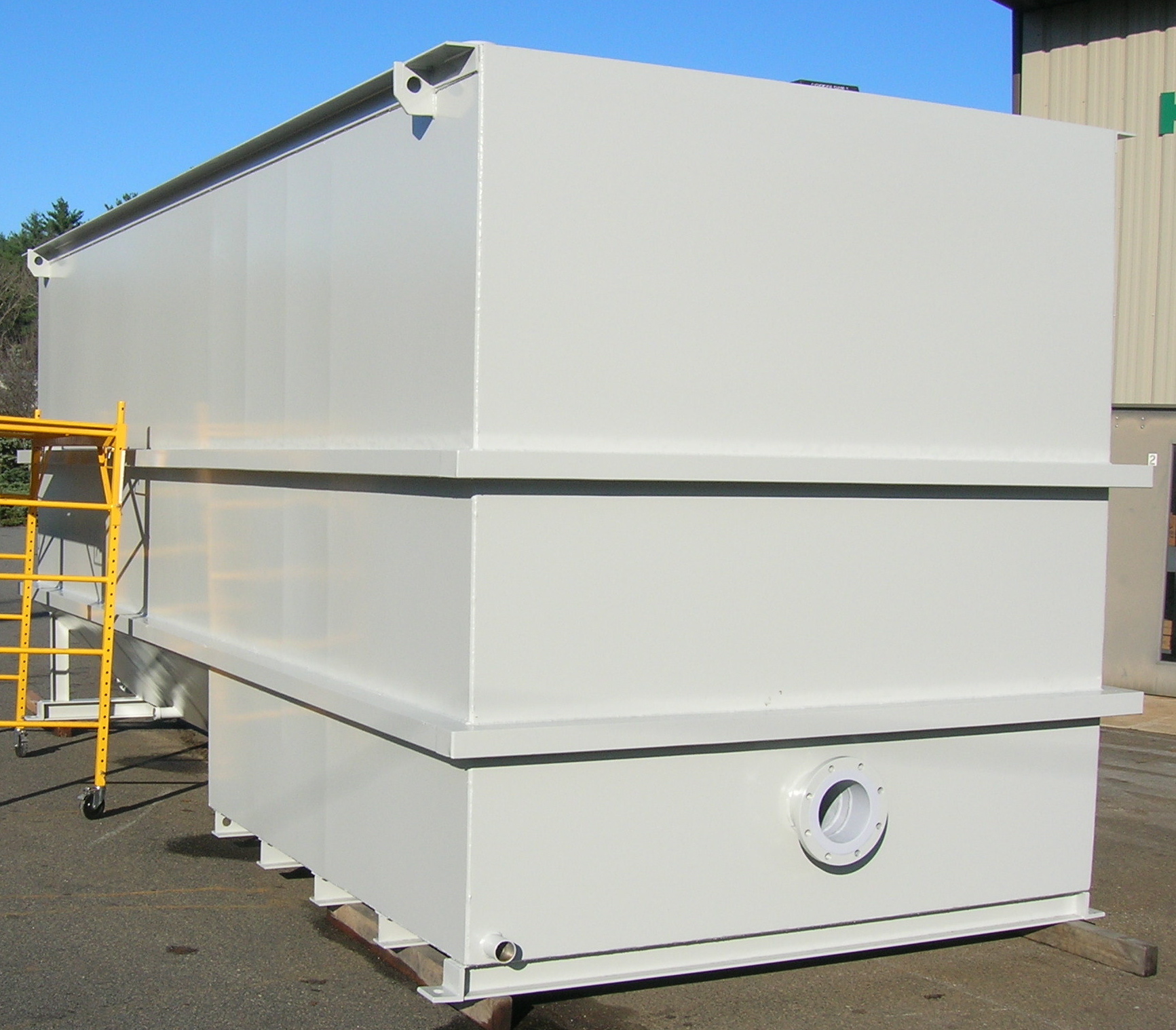
Stage 1, Inlet Area – The water mixture flows into the inlet quiescent area where the velocity of the water slows. The free oil (150 micron in size or greater) separates and rises to the surface where it is removed by a pipe skimmer.
Stage 2, Clarifier/Solids Intercept Section – The settleable solids flow downward and are captured in the clarifier/ solids intercept section.
Stage 3, Inclined Plate Section – The suspended solids and dispersed oil flow upward through the inclined plates section. Most of the suspended solids will slide down these plates into the hopper.
Stage 4, Separation Compartment – The remaining suspended solids and dispersed oil flow into the separation compartment where the coalescing plates remove 99% of the free oil droplets 30 micron or greater. This oil rises to the surface where an oil skimmer decants it to an oil storage tank. The coalescing plates then capture the remaining suspended solids.
Stage 5, Clean Water Compartment – The flow of water will go over the overflow weir into the clean water compartment where oil absorption polishing bags trap any trace oils before the water is discharged.
| Model | BPD (Barrels Per Day) |
GPM | Width | Length | Height | Inlet Outlet Dia |
Clarifier Plate Area, SF |
Separator Coalescing Volume, CF |
Sludge Volume (Gal) |
Total Capacity (Gal) |
|---|---|---|---|---|---|---|---|---|---|---|
| SOWS-150 | 5,140 | 150 | 6′-6″ | 20′-0″ | 9′-0″ | 6″ | 600 | 64 | 300 | 4250 |
| SOWS -200 |
6,850 | 200 | 6′-6″ | 20′-0″ | 10′-0″ | 6″ | 800 | 80 | 300 | 4930 |
| SOWS -250 |
8,570 | 250 | 7′-6″ | 20′-6″ | 10′-0″ | 8″ | 1000 | 96 | 350 | 5810 |
| SOWS -300 |
10,285 | 300 | 8′-6″ | 21′-6″ | 10′-0″ | 8″ | 1200 | 120 | 400 | 7040 |
| SOWS -350 |
12,000 | 350 | 8′-6″ | 23′-0″ | 10′-0″ | 8″ | 1400 | 150 | 425 | 7480 |
| SOWS -400 |
13,715 | 400 | 8′-6″ | 24′-6″ | 11′-0″ | 8″ | 1600 | 150 | 500 | 8500 |
| SOWS -450 |
15,430 | 450 | 9′-6″ | 26′-0″ | 11′-0″ | 8″ | 1800 | 175 | 525 | 10020 |
| SOWS -500 |
17,140 | 500 | 9′-6″ | 26′-6″ | 11′-0″ | 8″ | 2000 | 210 | 550 | 10450 |
| SOWS -550 |
18,855 | 550 | 9′-6″ | 28′-0″ | 12′-0″ | 8″ | 2200 | 210 | 675 | 11580 |
| SOWS -600 |
20,570 | 600 | 9′-6″ | 29′-6″ | 12′-0″ | 10″ | 2400 | 240 | 700 | 13240 |
| SOWS -700 |
24,000 | 700 | 10′-6″ | 30′-0″ | 12′-0″ | 10″ | 2800 | 288 | 750 | 15450 |
| SOWS -800 |
27,425 | 800 | 10′-6″ | 31′-0″ | 12′-6″ | 10″ | 3200 | 324 | 775 | 17540 |
| SOWS -900 |
30,860 | 900 | 10′-6″ | 32′-6″ | 13′-0″ | 12″ | 3600 | 324 | 800 | 19260 |
Choosing the right oil water separator can seem daunting. Just as not all applications are alike, not all separators are made alike. Customers should understand a few important points to make sure they’re getting what they pay for.
Oil Water Separators are designed to effectively remove floating solids and non-emulsified oil from an oil and water mixture on a beginning to end flow process through the separator. The mixture of oil and water enters one end of the separator and slowly flows toward the other end. If oil and water are mixed and not emulsified, the oil originally exits the water in different sizes of droplets. When the drops of oil are large enough and the flow is laminar, or moving in a smooth and gentle flow with no turbulence, the oil droplets will separate before reaching the end of the separator tank.
Since the calculations of Stokes’ Law are supported on a zero velocity flow, a Reynolds number lower than 500 guarantees optimal separation. The majority of oil water separators commonly use the parallel corrugated plate design which causes oil droplets to enlarge in size and ascend to the surface of the water. Flow of oil and water through the oil water separator follows several main steps after entering the separator:
It is especially essential for the flow of the liquid through the oil water separator to be laminar to act in accordance with Stokes Law. To achieve this type of flow, a design that is cross-fluted and having an internal structure of connecting channels between adjoining plates can be used. With this design and the enlarged surface area, the effectiveness of the oil water separation process is greatly enhanced.

Oil and water separator systems and water reclaim systems are generally used in commercial settings to remove oil and solids from wastewater effluents. Electrical substations, chemical plants, and oil refineries utilize this technology every day. There are two main types of systems, sewer pre-treat systems and closed-loop systems. Sewer pre-treat systems will treat and clean the water so that it can be discharged into the local sewer system. A closed loop system will treat the water so that it can be reused onsite.
In an oil water separator, the corrugated plates intercept oil droplets as the wastewater travels through the separator. New droplets coalesce (combine) with retained droplets, and the droplets become larger. Enlarged droplets are released from the water and rise to the surface where they are decanted into a storage tank, and then properly disposed of with any local or government waste management facility.
Washbay Solutions offers a complete line of the best oil water separators and water reclaim systems on the market today. Whether above or belowground, a closed-loop or sewer pre-treat system, Washbay Solutions has the right system to fit the needs of your company.
A case study was conducted of our sewer pre-treat system at one of our customers located in one of the strictest sewer authorities in North Carolina. After assisting our customer with obtaining a permit, we also helped save them thousands of dollars on a water meter required by the permit. Our client was very pleased with the system, and we returned quarterly to assist with and coordinate water analyses required by their permit. As the water analyses results kept proving our system was cleaning the water remarkably well, the permit requirements kept decreasing which saved our client thousands of dollars in analyses costs.
Another case study was conducted of our closed-loop system at a trucking company. Since they were located outside of the local sewer limits, they needed to be able to clean and recycle their own wastewater. In May of 2007, we assisted the trucking company with the installation of a closed-loop water reclaim and separation system that is used on a daily basis today. We still provide quarterly inspections to ensure the closed loop system is working as designed.
Whether your company is looking for a closed-loop or a pre-sewer treatment system, Washbay Solutions can help design the system that is right for you.