We provide heavy-duty, multi-stage, closed loop and hybrid wash water treatment systems to clean
the wash water so it can be used over and over, saving thousands of gallons of water per year and
associated discharge costs.
The system can be designed in two ways. The first option is a complete closed-loop system with no
sewer discharge. With these systems, 100% of the water used by the pressure washers,
demuckers, and water cannons is recycled. As water is carried off with equipment, evaporated into
the air, or blown off the wash bay due to wind, make up water is added to the system to offset these
losses.
The second option is a hybrid closed-loop system. In our hybrid systems, water is recycled for the
de-mucking and/or water cannons, but fresh water is fed to the pressure washers. If the pressure
washer adds so much water to the system that all water storage tanks are filled to the maximum
level, any additional excess water is treated with carbon and sent to the sewer system.
Both systems are part of our comprehensive approach to water treatment that includes solids
settling, oil and grease removal, water filtration, odor control, and final polishing.
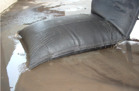
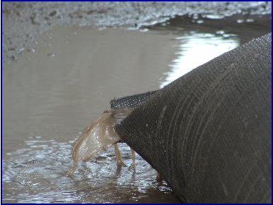
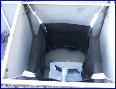
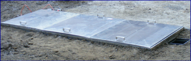
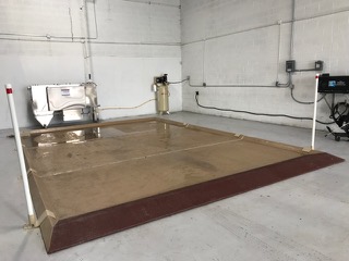
Stage 1 – Solids Settling
We help you develop site-specific solutions to eliminate as many solids as possible before the water
goes to the next stage of filtration. Solutions include sumps, basins, trenches or screening systems
that are custom-designed for your facility, washing processes and maintenance procedures.
 |
 |
|
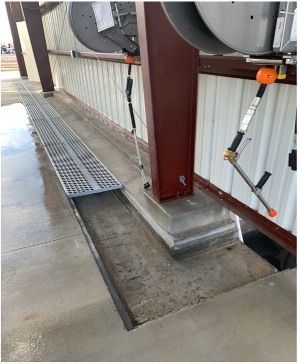
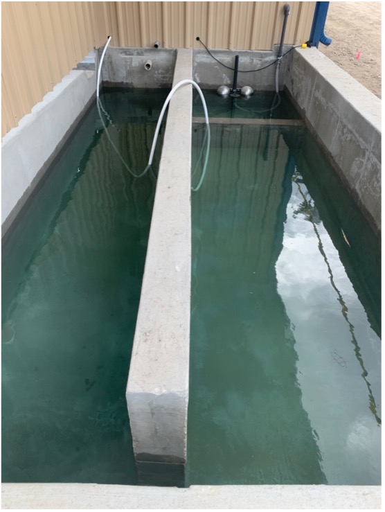
| Solids Handling Trench System | Solids Handling Basin System |
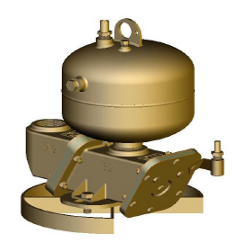
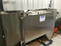
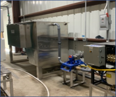
Stage 2 – Oils, Grease & Solids Removal
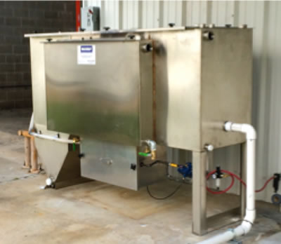
After the coarse solids settling, the water is processed through a multi-compartment stainless steel clarifier oil-water separator, which separates out smaller suspended solids, oil and water. In the first compartment, free oils float to the surface. In the second section, the stainless steel clarifying plates remove coarse amounts of oil and as much Total Suspended Solids (TSS) as possible. The angles of the non-clogging plates are 55° which allows solids to slide down the plates into the solids hopper, where they can easily be pumped out. Next, the water goes through our coalescing media which removes essentially 100% of all free and dispersed non-emulsified oils so the FOG effluent concentration can be as low as 5 ppm.
 |
 |
|
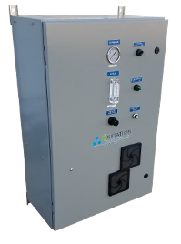
| SPT-10 Clarifier Oil Water Separator | SPT-30 Clarifier Separator with Pump & Control |
Stage 3 – Water Filtration & Odor Control
After the clarifier oil-water separator, the water is pumped though several filtration steps including multi-media (sand, gravel, anthracite), blended activated carbon, polishing filter, and corona discharge ozone. These filters reduce odors and any contaminants to fewer than 10 microns in size, including emulsified oils, waxes, and other volatile organic compounds. Media, carbon, ozone and water storage volumes are typically customized to meet your particular application.
Stage 4 – Final Polishing Filtration
In the final polishing filtration section of the CT system, water is pumped from the storage tank
through a blended activated carbon bed (customized for your application) and then through a final
cartridge filter. When the pressure washers require water, the pump will provide clean, treated
water, free of particles, substantially all emulsified oils, waxes and other volatile organic compounds.
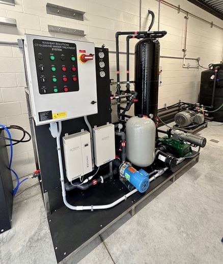
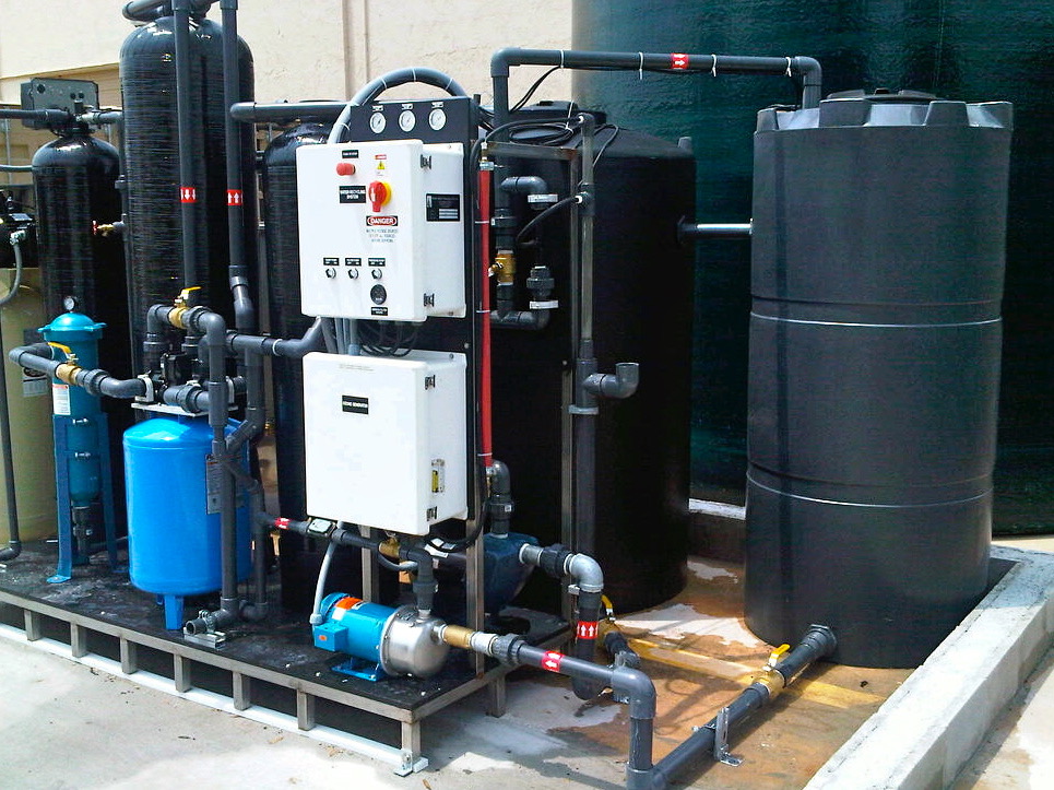
Closed Loop System Features
- 10-100 GPM Design Flow (Larger systems are available)
- Non-Ferrous Construction – Stainless Steel, PVC, Fiberglass
- Fully-Automatic, pre-wired
- Multi-Stage / Multi-Pass Filtration
Clarifier Separator System
- Stainless Steel Clarifier Oil/Water Separator with 55° Hopper
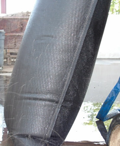
- Advanced coalescing media designed to remove oil droplets greater than 20 microns
- Electric or Air Diaphragm pump with controller
Closed Loop Filtration System
- Automated Self-Cleaning Multi-Media and Carbon Fiberglass Filter Tanks
- Heavy-duty, high efficiency Re-Circulation Pumps
- Heavy-duty high efficiency Re-Pressurization Pumps
- Transfer pump to pump water from clarifier separator to system
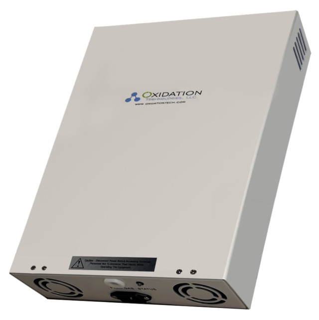
- Heavy-duty Ozone System to control odors (up to 32 gms per hour)
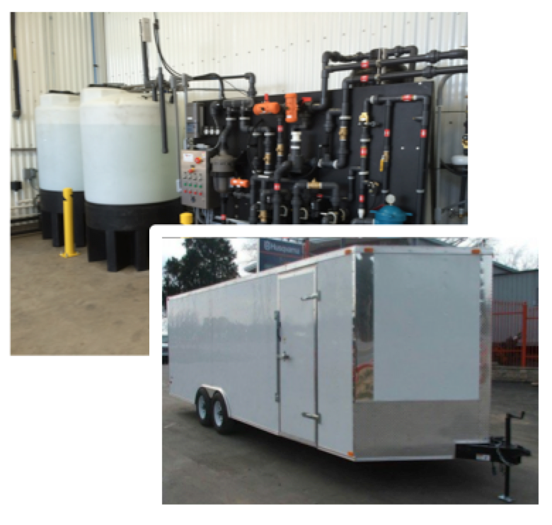
- (2-3) Poly water storage tanks – UV Protected
- Sensors and interconnecting Schedule 80 plumbing
- UL-Listed NEMA-4X control panel
- PLC controller for automatic back wash operations
- All components mounted on heavy-duty stainless steel skid
Optional Features
- Additional water storage tanks
- Bag filters
- Transportable equipment rooms
- Rain Diverter Systems
- pH control system
- TDS monitoring system
- Electric disk skimmers
- Automatic sludge dump systems
- Corrosion protection packages for high salt or corrosive applications
 |
 |
|
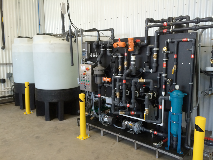
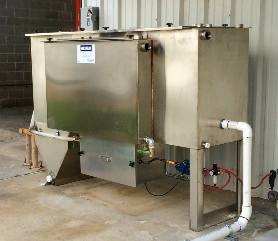
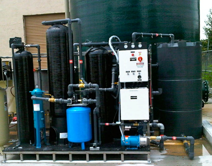
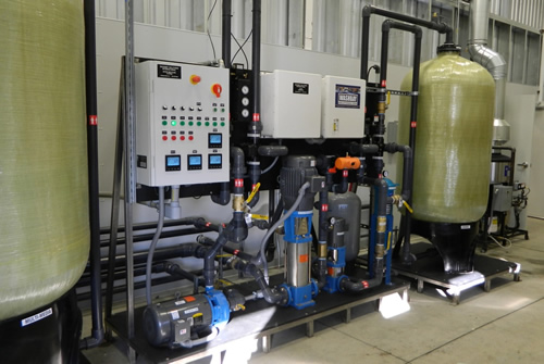
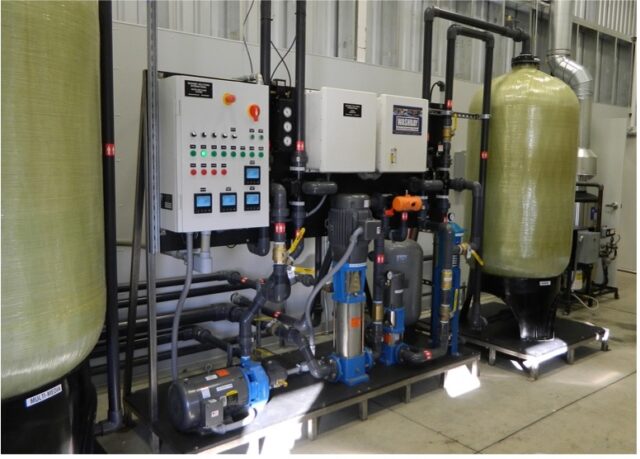
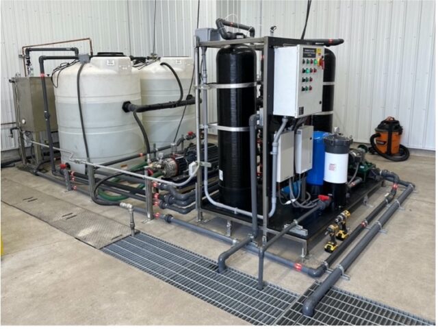
| CT-65 – 65 GPM Closed Loop Treatment System | CT-10 – 10 GPM Closed Loop Treatment System with Tanks & Separator |
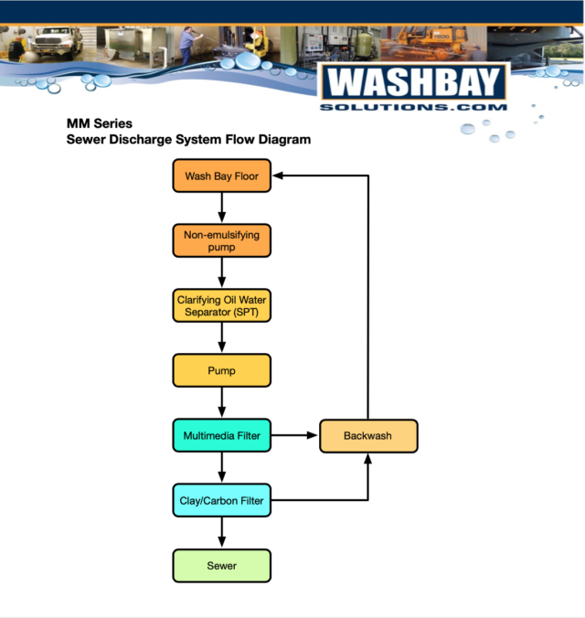
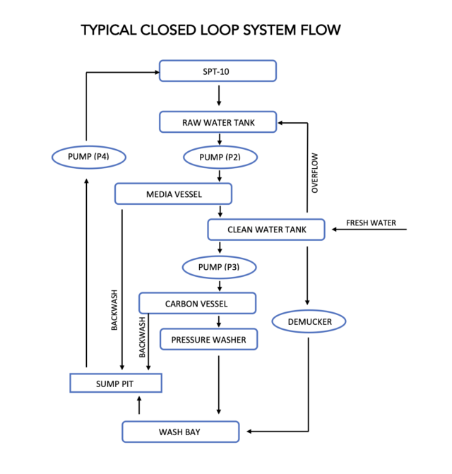
Typical Closed Loop System Flow Process
TYPICAL CLOSED LOOP SYSTEM SPECIFICATIONS
| MODEL | CT-10/10 | CT-35/20 | CT-65/50 | CT-100* |
| DESIGN FLOW RATE, GPM | 1-10 | 1-25 | 10-55 | 30-100 |
| COALESCING PLATE AREA, SF | 41 | 124 | 211 | 400 |
| COALESCING MEDIA, CF | 4 | 8 | 24 | 48 |
| CLARIFIER SEPARATOR SIZE, FT (WxLxH) | 3 x 7 x 5 | 3.5 x 8 x 6 | 4 x 10 x 6 | 5 x 11 x 7 |
| NON-EMUSIFYING INFLUENT PUMP, GPM MAX | 20 | 50 | 75 | 125 |
| MULTI-MEDIA, LBS | 300-500 | 500-1000 | 2500-2600 | 3700-4200 |
| ACTIVATED CARBON, CF | 4-15 | 10-40 | 20-40 | 40 |
| POLISHING FILTER, SET | 1 | 1 | 1 | 1 |
| RECLAIM RE-CIRCULATION PUMP, HP | 1.5 | 1.5 | 3 | 5 |
| RECLAIM RE-PRESSURIZATION PUMP, HP | 1 | 3 | 5 | 7.5 |
| DIRTY WATER STORAGE VOLUME, GAL | 500-750 | 500-1000 | 750-1500 | 1000-2500 |
| CLEAN WATER STORAGE VOLUME, GAL | 500-750 | 500-1000 | 750-1500 | 1000-2500 |
| OZONE SYSTEM, GRAMS/HR | 8-16 | 8-32 | 16-32 | 32 |
| RECLAIM CONTROL SYSTEM | PLC, Automatic, Manual or Off | |||
| RECLAIM PUMP FRAME SIZE, FT (WxLxH) (TANKS ADDITIONAL) |
4 x 6 x 6.5 | 4 x 8 x 8 | ||
| POWER REQUIREMENTS | 208 / 240 V 1 ph or 208 / 240 / 480 V 3 ph | |||
* LARGER CAPACITY SYSTEMS (200-1500 GPM) ARE AVAILABLE
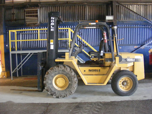
APPLICATIONS:
- Commercial Trucking
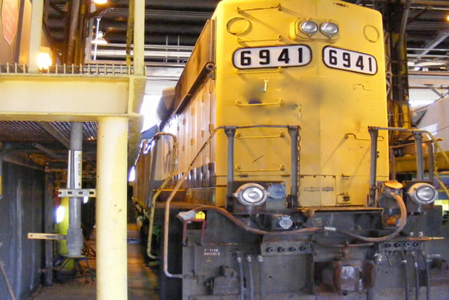
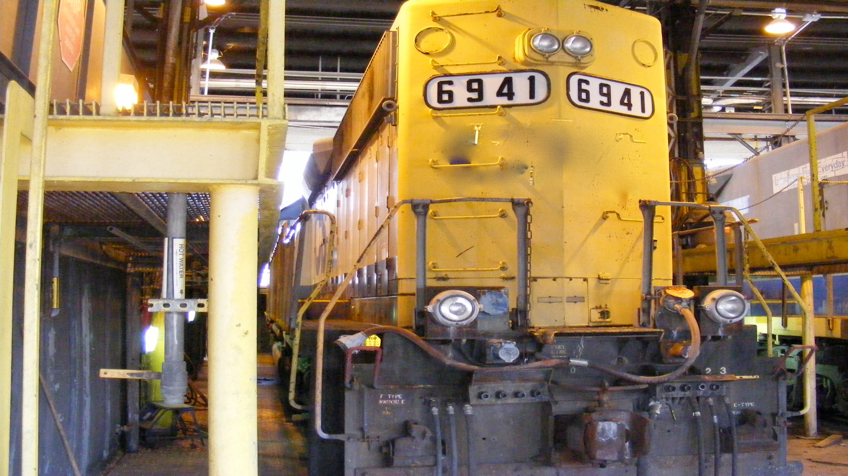
- Locomotive
- Mining
- Marine
- Forklift
- Oil and Gas Drilling