featured

May 13, 2022
solids-settling-below-ground-oil-water-separators-1280x427.png

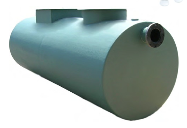
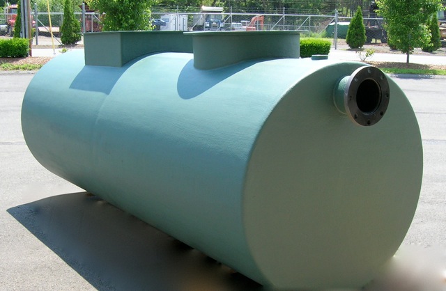
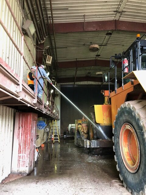
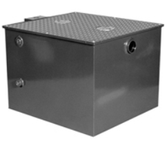
Our new solids settling below ground separator is ideal for any application with high concentration of solids and oil in water.

Most old conventional separators require long retention times, resulting in needlessly large units. They also have little in the way of solids settling. Our new innovative new design has both a much smaller footprint and a much higher removal efficiency for both oil and solids which lowers your total cost of ownership.

How it works:

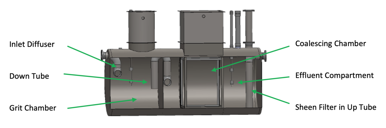
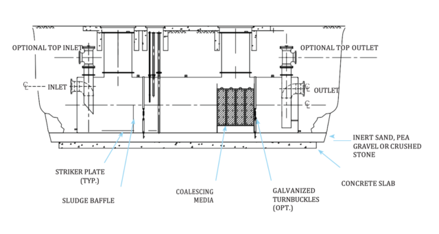
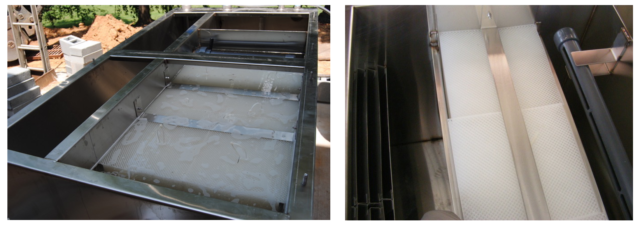
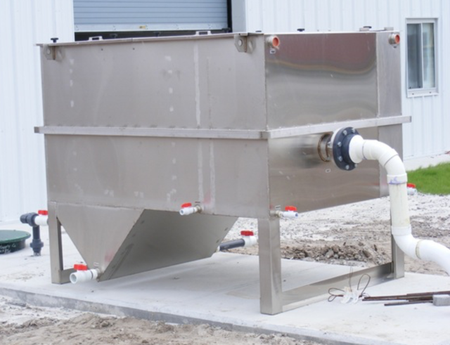
To enhance separation, these separators contain an inlet diffuser, grit chamber/inlet compartment, down tube, coalescing/separation chamber, oil storage area, effluent compartment, and sheen filter.

Series WB-ES Solids Settling, Below Ground Oil Water Separators

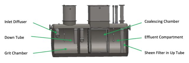
  • In the Grit Chamber, the inlet diffusor initially distributes the incoming water flow evenly over the cross-sectional area of the separator. The free oil (150 micron size or larger) is separated and the settleable solids are captured at the bottom.
  • The suspended solids and dispersed oil then flow upward through the down tube in the Grit Chamber, and over to another diffusor in the Coalescing Chamber.
  • The flow continues through the Coalescing Chamber where the coalescing plates will separate the oil droplets 30 micron size and larger up to the surface, and the remaining suspended solids will be captured beneath the coalescing plates.
  • Finally, a removable Sheen Filter inside the up tube in the Effluent Compartment will remove carryover, smaller droplets of oil, and mechanical emulsions.

Performance Standards

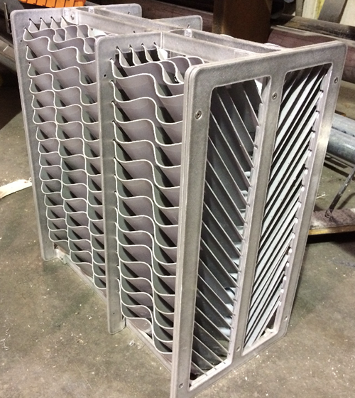
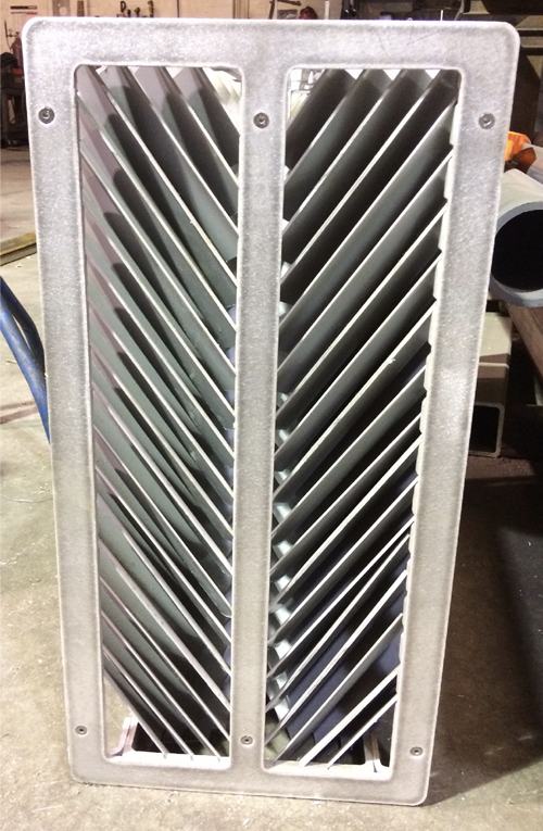
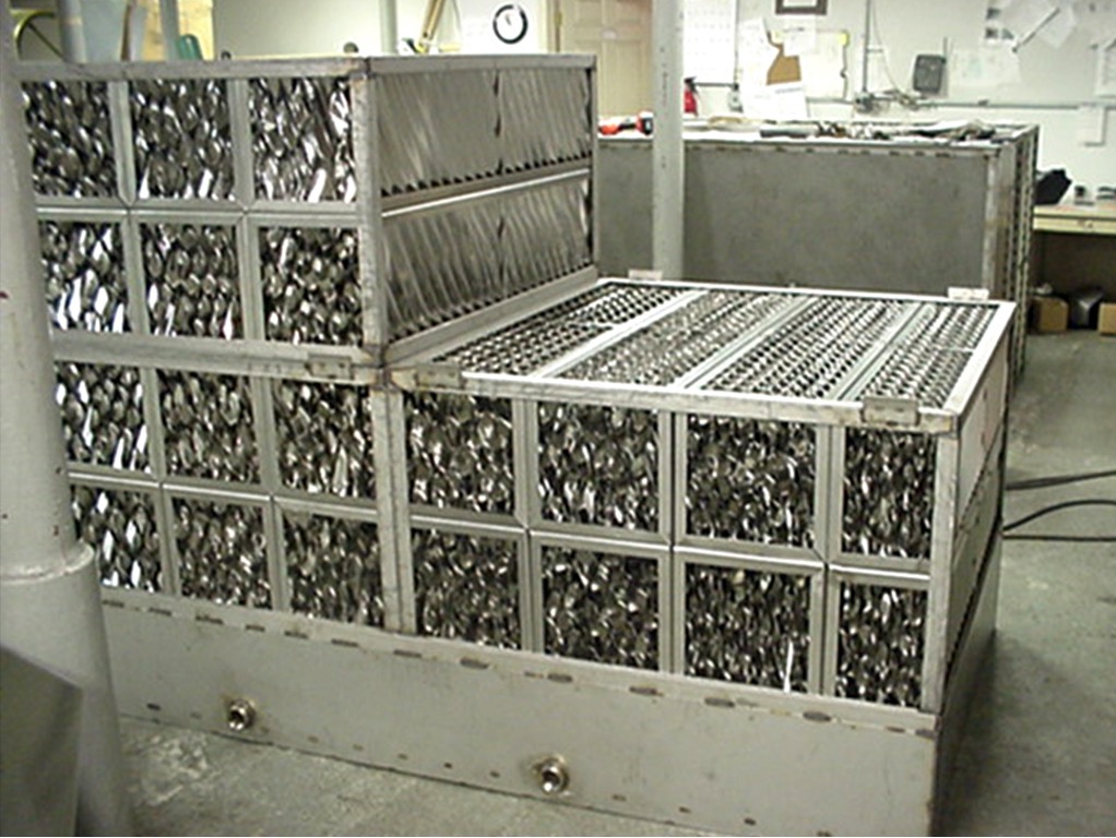
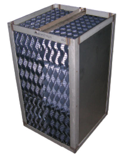
  • Utilizes patented, revolutionary, non- plugging coalescing plates which remove free oil droplets as small as 30 microns
  • Performance guarantee based on influent characteristics
  • Will achieve discharge of 5 ppm or less in accordance with CEN EN 858-1
  • Warranted for (1) year on material and workmanship and (10) years against external corrosion


Below Ground Oil Water Separator Models

Model # Average Flow Rate (GPM) Capacity

(Gallons)

Inlet/Outlet (Inches) Dimensions, D x L (Feet)
WB-QB-35-ES 35 350 4 3.5 X 6
WB-QB-55-ES 55 550 4 4 X 6
WB-QB-100-ES 100 1000 6 4 X 10.75
WB-QB-200-ES 200 2000 6 5.3 X 12
WB-QB-300-ES 300 2500 6 5.3 X 15
WB-QB-400-ES 400 3000 8 5.3 X 18
WB-QB-500-ES 500 3800 8 6 x 17.5
WB-QB-600-ES 600 4000 10 6 x 18.75
WB-QB-700-ES 700 7000 10 8 X 18.67
WB-QB-800-ES 800 7000 10 8 X 18.67
WB-QB-900-ES 900 7000 12 8 X 18.67
WB-QB-1000-ES 1000 7500 12 8 X 20
WB-QB-2000-ES 1200 8500 12 8 X 22.5
WB-QB-1500-ES 1500 12000 16 10 X 20.75
WB-QB-2000-ES 2000 14000 18 10 X 24
WB-QB-2500-ES 2500 17000 18 10.5 X 26.5
WB-QB-3000-ES 3000 19000 20 10.5 X 29

         Call Now to Speak with a Oil Water Separator Specialists – 1-800-453-8639!


May 6, 2022
below-ground-oil-water-separator-design.jpg

Our single wall or double wall below ground parallel, corrugated plate oil/water separators meet and exceed API 421 requirements, removing essentially 100% of dispersed non-emulsified oil droplets in the waste stream.

These separators are special purpose prefabricated parallel corrugated plate, cylindrical, gravity displacement oil water separators, containing an inlet compartment, sludge chamber, separation chamber, oil storage area and clean water compartment.

As shown below, the separation process if fairly simple. Wastewater flows into the inlet compartment. A baffle interrupts the flow and allows solids to drop out. Next the oil water moves into the separation chamber where our innovative media causes small oil droplets entrained in the water to coalesce into larger ones which then separate from the water and float to the surface. The clean water then travels into the clean water compartment through the outlet to the sewer.

Features

  • Patented, revolutionary, non- plugging coalescing plates which remove free oil droplets as small as 20 microns
  • Single wall or double wall construction with interstitial space for leak detection
  • Rectangular access manhole with 3’ extension to service and maintain coalescing media
  • Fittings for vent, oil pump out, sludge pump out, gauging and lifting lugs
  • Exterior sandblasted and coated
  • Will achieve discharge of 5 ppm or less in accordance with CEN EN 858-1
  • Warranted for (5) years on material and workmanship and (30) years against external and internal corrosion
  • Construction in accordance with UL58 and corrosion protection in accordance with UL1746
Below Ground Oil Water Separator Design
Featuring one of our oil water separator designs to be placed under ground.

Options

  • Internal coating for corrosion protection
  • Grit chamber for high solids applications
  • Hold down straps
  • Leak and Level detection systems

Applications

  • Parking Lots
  • Re-fueling Facilities
  • Marinas
  • Military Installations
  • Truck and Equipment Washes

How does it work?

Analysis

With these separators, we can provide analysis, which indicates that the separator will be provided with the required square feet of projected plate separation area to achieve the specified performance under laminar flow (i.e. Reynolds Number of less than 500) conditions. This service can include calculations signed by a registered professional engineer.

Underground Oil Water Separator Specifications
Model # Average Flow Rate (GPM) Capacity (GALLONS) Dimensions, D x L (FT)
WB-QB-342 35 350 3.5 x 6
WB-QB-548 55 550 4 x 6
WB-QB-1048 100 1000 4 x 10.75
WB-QB-2064 200 2000 5.3 x 12
WB-QB-3064 300 3000 5.3 x 18
WB-QB-4064 400 4000 5.3 x 24
Larger sizes available.

Underground Oil Water Separator Specifications

Frequently Asked Questions


February 16, 2022
treat-wash-water-technology.jpeg


Designed to remove extensive contamination, our heavy-duty, multi-stage, discharge treatment systems treat wash water so it can be safely discharged to the sewer or, in many cases, the surroundings.

Stage 1 – Solids Settling 


Advanced Technology for treating washwater

Almost all commercial washing operations produce some solids so the first stage of our filtration process is the solids handling system. We help you develop site-specific solutions to eliminate as many solids as possible before running the water through to the next stage of filtration. Solutions include custom-designed sumps, basins, trenches or screening systems.

Stage 2 – Oils & Solids Separation 

After the coarse solids settling, the water is processed through either a multi-compartment stainless steel oil water separator or a stainless steel clarifier oil-water separator, which separates out smaller suspended solids, oil and water. In the first compartment of the clarifier oil water separator, free oils float to the surface.  In the second section, the stainless steel clarifying plates remove coarse amounts of oil from the waste stream and remove as much Total Suspended Solids (TSS) as possible.  The angles of the non-clogging plates are 55° which will allow any solids to slide down the plates into the solids hopper, where they can easily be pumped out.   Finally, the coalescing media removes essentially 100% of all free and dispersed non-emulsified oils so the FOG effluent concentration can be as low as 5 ppm.

Stage 3 – Water Filtration & Polishing

After the clarifier oil-water separator, the water is pumped though a multi-media (sand, gravel, anthracite) filter and then safely discharged to the sewer or surroundings. Processed water passing through the system will be free of substantially all emulsified oils, waxes and other volatile organic compounds with only limited soaps and detergents remaining in the treated water. If needed, a blended activated carbon or a carbon/clay mixture tailored to a particular waste stream can be added as an optional polishing filter.

System Features

  • Non-Ferrous Construction – Stainless Steel, PVC
  • Fully-Automatic, pre-wired
  • Clarifier Separator System
    • Stainless Steel Clarifier Oil/Water Separator with 55° Hopper
    • Advanced European coalescing media designed to remove oil droplets greater than 20 microns
    • Electric or Air Diaphragm pump with controller
  • Discharge Filtration System
    • Automated Self-Cleaning Multi-Media and/or Clay/Carbon Fiberglass Filter Tank
    • Heavy-duty, high efficiency Pump
    • Sensors and interconnecting Schedule 80 plumbing
    • NEMA-4X  control panel
    • PLC controller for automatic back wash operations
    • All components mounted on heavy-duty stainless steel skid

Depending on the location, many options are available to maximize the efficiency of the wastewater treatment system including:

Optional Features

  • Can be configured with existing equipment
  • SCADA and remote monitoring UL/CSA Listing
  • Transportable equipment rooms
  • Rain Diverter Systems
  • Chemical/Acid/Salinity Resistant Pumps & Components
  • pH control system

TYPICAL MM-SERIES SYSTEM SPECIFICATIONS

MODEL

MM-10/10

MM-35/20

MM-65/50

MM-100*

DESIGN FLOW RATE, GPM

1-10

1-25

10-55

30-100

COALESCING PLATE AREA, SF

41

124

211

400

COALESCING MEDIA, CF

4

8

24

48

CLARIFIER SEPARATOR SIZE, FT (WxLxH)

3 x 7 x 5

3.5 x 8 x 6

4 x 10 x 6

5 x 11 x 7

NON-EMUSIFYING INFLUENT PUMP, GPM MAX

20

50

75

125

MULTI-MEDIA, LBS

300-500

500-1000

2500-2600

3700-4200

OPTIONAL POLISHING CLAY/CARBON, CF

4-15

10-40

20-40

40

FILTER PUMP, HP

1.5

2

3

5

DIRTY WATER STORAGE VOLUME, GAL

500-750

500-1000

750-1000

1000-1500

CONTROL SYSTEM

PLC, Automatic, Manual or Off

PUMP FRAME SIZE, FT (WxLxH)
(TANKS ADDITIONAL)

3 x 6 x 6.5

3 x 8 x 8

POWER REQUIREMENTS

208 / 240 V 1 ph   or  208 / 240 / 480 V 3 ph


* LARGER CAPACITY SYSTEMS (200-1500 GPM) ARE AVAILABLE


APPLICATIONS:


January 21, 2022
heavy-demucking-water-cannon.jpg

This video shows our MM-20/850 Mighty Monitor Demucker System in operation in northern Canada. Trucks come in caked with grit, frozen mud and snow.


Using the hand-held wand, the operators can easily vary the flow from stream to cone to safely and effectively wash all parts of the vehicle.

Since the MM-20/850 produces a powerful 20 gpm @ 850 psi stream, this type of cleaning is much quicker than using a standard pressure washer.

Highly recommended for the cleaning of heavy construction or mining equipment and trucks, our revolutionary demucking systems clean with the power of a fire hose but use a fraction of the water.

Our demuckers will quickly remove heavy accumulations of dirt, clay, ice, and mud from all sorts of equipment – saving both time and water.  Depending on your application, we have smaller units with flowrates from 8 to 20 gpm and pressures from 300 to 2000 psi. All of them are much quicker than a standard pressure washer!

All types of demucking can be done by easily switching from a long-range stream to a close-up cone stray with a click of the wand.

This video shows our MM-20/1000 Mighty Monitor Demucker System operating in northern Canada. Trucks come in from the field caked with grit, frozen mud and snow and leave a short time later, clean and ready for service.

DEMUCKER SYSTEM SPECIFICATIONS

Demucking System MM-20/850 MM-20/300 MM-8/1000 MM-10/2000
Max Flow Rate & Pressure 20 GPM @ 850 PSI 20 GPM @ 300 PSI 8 GPM @ 850 PSI 10 GPM @ 2000 PSI
Uses Fresh or Recycled Water Both Both Both Both
Motor, HP 15 7.5


7.5 15
Pump Type Industrial, heavy-duty positive displacement Industrial, heavy-duty positive displacement


Industrial, heavy-duty positive displacement Industrial, heavy-duty belt driven positive displacement
Controls Manual/Remote/PLC Manual/Remote/PLC


Manual/Remote/PLC Manual/Remote/PLC
Gun/Wand/Hose Handheld Stream-to-Cone Wand, 50’ L @ ¾” D hose Handheld Stream-to-Cone Wand, 50’ L @ ¾” D hose


Handheld Stream-to-Cone Wand, 50’ L @ 1/2” D hose Handheld Stream-to-Cone Wand, 50’ L @ ¾” D hose


Feed Tank Optional Optional Optional Integrated 100 gallon poly tank w/ low water shut-down
Electric 208/480/575 V 3 PH 50/60 HZ 208/480/575 V 3 PH 50/60 HZ 208/480/575 V 3 PH 50/60 HZ 208/480/575 V 3 PH 50/60 HZ
Approximate Dimensions 5’ L x 2’ W x 2’ H 5’ L x 2’ W x 2’ H 5’ L x 2’ W x 2’ H 2’ L x 2’ W x 4’ H

MM-20/1000 Mighty Monitor Demucker System

  • 20 GPM @ 850 psi, demucking station
  • High efficiency diaphragm pump
  • 15 hp TEFC motor
  • NEMA 4X control panel
  • Pressure gauge
  • 50’ x 3/4” High Pressure Hose
  • Long range adjustable stream to cone, wand/gun assembly
  • Stainless steel frame
  • Utilities required Power: 480V/3 PH/60 Hz 25 amp; 230V/3 PH/60 Hz 50 amp
  • Approximate dimensions: 18” W x 60” L x 24”H

Call for more information at 800-453-8639.


January 21, 2022
spt-75-clarifier-oil-water-separator.jpeg

SPT-75 Clarifier Oil Water Separator

We have developed a revolutionary heavy-duty wash and treatment system by integrating our demucking system with our clarifier oil water separator system.

Using low flow pumps, moderate pressure and specialized nozzles, our robustly- designed demucker systems can quickly clean large trucks, tracked vehicles or any heavy equipment caked with mud, clay, ice, or muck – using only 20 gpm of water.

After washing, we can then process this water through our stainless steel clarifier oil water separator to reduce your environmental liabilities. Even though full of solids, oils and grease, our separator will effectively treat this wash water for re-use or discharge. 

Fast and effective cleaning with low water treatment costs – definitely a win-win situation!

Features:

  • High-Efficiency Diaphragm or Multi Stage Pump, 20 GPM @ 850 PSI
  • Stainless Steel Construction
  • NEMA 4X Integrated Control Panel
  • Multi-directional Stream-to-Cone Gun & Industrial grade hose reel
  • Poly water storage tank
  • Stainless steel clarifier separator designed to remove 99% of oil droplets
  • Inclined plates to remove solids
  • Sludge hopper to capture and contain settleable solids
  • Electric or Air diaphragm transfer pump
  • Internal oil storage tank

Optional Features Available:

  • UL Listings
  • Remote Motor Controls
  • Heating Systems
  • Automated Wash Monitors
  • Portable Wash Containment Pad
  • Odor Control Systems
  • Polishing Packs

Reduce your environmental liabilities and get the power of a wash monitor with a fraction of the water usage!

SYSTEM SPECIFICATIONS

Pumping System

DTS-20

Max Flow Rate & Pressure          

20 GPM @ 850 PSI

Uses Fresh or Recycled Water

Both

Motor, HP

15

Pump Type

Electric Diaphragm

Controls

Manual/Remote/PLC

Hose

50-75’ L @ ¾” D

Gun/Wand

Handheld Stream-to-Cone

Water Storage

500 Gallon Poly Tank

Industrial Grade Hose Reel

Manual, Spring Rewind, Portable

Electric

120/208/480/575 V 3 PH 50/60 HZ

Approximate Dimensions (with tank)

8’ L x 4’ W x 7’ H


Clarifier Oil Water Separator


Max Flow Rate

20 GPM

Internal Tank Capacity

650 Gallons

Sludge Capacity

27 Gallons

Coalescing Media

6 Cubic Feet

Pump Type

Air or Electric Diaphragm

Controls

Air or Electric Manual/Remote/PLC

Air/Electric

8-14 cfm at 40 psi/120/208/480/575 V 3 PH 50/60 HZ

Approximate Dimensions

8’ L x 3’ 6” W x 6’ H

Demucking Pumps and Custom Piping System

August 25, 2021
pressure-washing-demucking.png

“I also want to let you know how impressed I was with all of the JDI equipment. Every piece of equipment you provided was exceptionally well constructed. I am thoroughly impressed with everything!”

“Everything I have seen and heard so far indicates that they are very happy with the demuckers. They are even creeping into the building and washing trucks every chance they get as ‘trial runs’, even before the contractor has officially turned the project over to them.”  – Brian S.                                                                                                        

Issues: A very large mining operation was rehabbing its existing wash pad and adding a new one. As with most mining operations, most of their vehicles are very large and, therefore, can carry a large amount of solids into the wash bay. These solids get caked into every surface of the vehicles.

The engineers designing their new building contacted us to assist with washing and treatment equipment and maximize their wash bay design.

Solution:  We worked closely with their engineers to first design a very efficient solids handling and settling system consisting of trenches, sumps and a settling basin.

Once we completed the design, we recommended a number of washing systems to augment their pressure washing systems.  Due to the fact that they had a variety of vehicles and equipment, they decided on dual 20 GPM @ 1000 psi demucking systems, an undercarriage wash and monitor system for washing. One demucking will be used also be used to supply the undercarriage wash system.

For their application, we also developed a very effective cleaning system which included multiple compact water monitors placed strategically in the wash bay. Each monitor system will supply 100 gpm @ 100 psi. For easy movement, the wash monitors are attached to custom steel trollies that are mounted on steel rails inside the wash bay.  It can be easily customized with a wide range of nozzles selections.

Since they would be washing in different wash areas, we then coordinated with the electrical engineers to integrate all of the remote controls so the systems could be easily controlled by a small crew.

After washing, the water is treated so that it can be re-used by a complete self-contained system, capable of processing 100 gpm.  It is a Closed Loop Carbon Treatment System so there is zero fluid discharge to the facilities’ surroundings.  The system includes a clarifier oil water separator to remove oils, ozone to remove odors and multi-level filtration to remove of particles greater than 10 microns in size, substantially all emulsified oils, waxes and other volatile organic compounds.

All of the systems were easily upgraded to meet mine safety standards.


June 24, 2021
oil-water-separator-media.png

CF-CP Media (Cross-Flow/Corrugated Plate) Oil Water Separator Media
Introduced a new coalescing media with a corrugated, cross-flow design.

In many washing applications, huge volumes of solids are generated during the washing process. This is especially true in the construction and mining industries. Some of the heavier solids drop out of suspension quickly while others get entrained in the oily wastewater.

To insure our oil water separators do not clog in these high solids washing applications, we have developed a new corrugated plate coalescing media with a cross-flow design.

This new media design is a series of plates curved in a simple wave shape. As the water enters the separator, the flow is directed evenly across the surface of the media plates. The solids are captured and fall to the trough area of the corrugated plates below and the oils rise and stick to the trough area of the plates above.

The separator design maintains laminar flow throughout the media so the oil and solids do not remix. Separated oil flows upwards along the plates to the top of the separator where it can be removed and solids slide down the smooth corrugated plates to the hopper area where they can be easily removed.

  • Available in stainless steel, PVC, HPVC and polypropylene
  • Plate spacing of ½”, ¾” or 1 ¼” depending on application
  • Supplied in blocks for easy installation and removal

By coupling high efficiency separation with easy maintenance of this new media, you will ensure your oil water separator operates at peak performance in high solids applications.

Give us a call at 800-453- 8639 for more information!

CF-CP Media (Cross-Flow/Corrugated Plate) Oil Water Separator Media
Site View of our new coalescing media with a corrugated, cross-flow design.


June 15, 2021
efficiency-coalescing-media-design.jpg

In some applications, a higher efficiency media is required for environmental concerns. This media uses its high surface to volume ratio to provide extremely efficient oil/ water/ solids separation.

This media is constructed of oleophilic coalescing plates arranged in a cross-fluted configura­tion that provides between 31–69 square feet of oil coalesc­ing surface and 7–17 square feet of solids settling area per cubic foot of media. Each plate has a series of angled ribs, which are sloped from the bottom of the separa­tion chamber to the top at a 60° angle establishing a com­pound inclined surface.

  • Available in stainless steel, PVC, HPVC, polypropylene and stainless steel
  • Vertical slant rib plate spacing of ½”, ¾” or 1 ¼” with slant ribs alternating direction by 90°
  • Supplied in 1’ cubes with optional stainless steel frames for easy installation and removal

The separator and media design maintains a sinusoidal laminar flow throughout the media so the maximum amount of oil separation is achieved. Coalesced oil can flow unimpeded along the plate surfaces to the top of the separator where it is easily removed.

Give us a call at 800-453- 8639 for more information!


June 10, 2021
coalescing-media-large.png

Our standard media has vastly superior properties compared to the traditional media used in oil-water separators. These properties result in a more efficient and effective separation than that attained by traditional coalescing media.

  • A larger amount of surface area per cubic foot of media allows for greater oil drop coalescence. This media has 132 ft2/ft3 surface area for oil droplets to contact. Other typical coalescing media have about 48 ft2/ft3 to 68 ft2/ft3.
  • A more efficient first step separation reduces the need for a second polishing step. Our media removes 99.9% of oil droplets 20 microns in size and larger. This meets EPA Method 1664 Revision A and European Standard EN 858-1.
  • An open design eliminates trapping of particles and subsequent clogging of water channels. Oil water separators with this media require fewer maintenance shut-downs and separates oil and water faster.
  • Where higher-than-normal operating temperatures are required, our media outperforms its competitors. It works effectively in temperatures up to 212°F, versus a maximum temperature of about 120°F for competing media.

Give us a call at 800-453- 8639 for more information!


January 25, 2021
standard-oil-water-separator-1280x981.png

Even though the terms “Oil Interceptors” and “Oil Water Separators” are often used
interchangeably, they are very different systems.

Interceptors

Oil interceptors
Oil interceptors are designed for use in drain lines where oils, sediment and other liquids are intercepted.

Oil interceptors are typically used in low flow drain lines where small quantities of oils, sediment
and other liquid contaminants can be “intercepted”. These drain lines may come from variety of
facilities including covered parking garages, machine shops, service stations, and manufacturing
facilities.

Usually constructed of steel, fiberglass or plastic, interceptors are simple systems which include a
baffle plate, a solids bucket, and a separation area. As the water enters the interceptor, a baffle
plate reduces the flow and turbulence of the incoming water which helps to drop out some solids
and sludge.

A low flow rate and little turbulence permits the oils and other light density to slowly separate from
the water and rise to the top of the separation area. From there, relatively oil-free water is
discharged to the sewer.

Oil Water Separators

In comparison, Oil Water Separators have a far more sophisticated and efficient design. They are used in higher volume applications such as industrial wash operations, parking lots, re-fueling facilities and military installations where there is a potential for a much higher volume of water, oil, and contaminants.

The standard oil water separator is a steel or stainless steel tank containing an inlet compartment, baffles system, sludge chamber, separation chamber with coalescing media, and clean water outlet chamber.

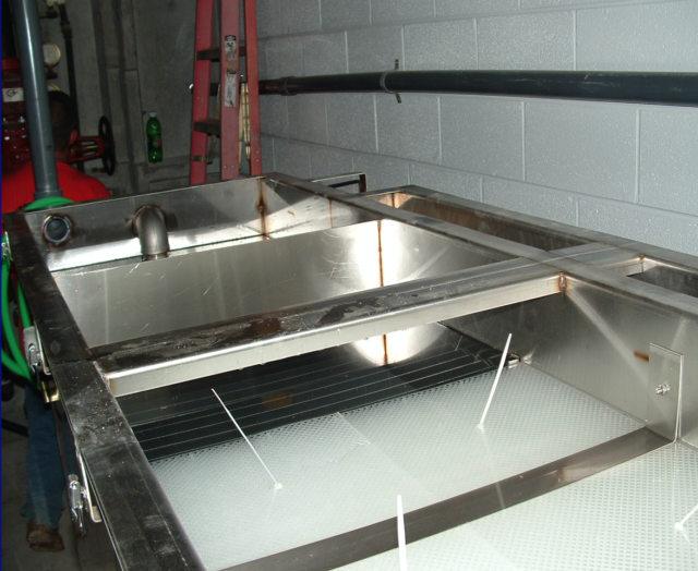
The water enters the inlet compartment where the oil separation process begins. Here, baffles slow down the water flow which causes some of the solids to drop out of suspension. Next, parallel corrugated coalescing media in the separation chamber cause the oil droplets in the water to coalesce together, and increase in size until they separate from the water. This coalescing media, with an internal structure of interconnecting channels, can remove essentially all free and dispersed, non-emulsified oils to an effluent concentration of less than 5 ppm – which is acceptable for discharge to most municipal sewer systems.


North Carolina

Headquarters

At WashBaySolutions.com, we have been specializing in high tech, custom-engineered solutions to complex washing and wastewater issues since 1991.
+ 1 800-453-8639

WashbaySolutions.com

sales@washbaysolutions.com

GET IN TOUCH

Follow Our Activity

Get the latest news, product updates and case studies all happening here: